当前位置:网站首页>STM32 advanced timer com event
STM32 advanced timer com event
2022-04-23 03:34:00 【Your youth my dream】
STM32 Advanced timer COM event - Software generation
STM32 Of COM Events are only for advanced timers TIM1 and TIM8 It works , Mainly for BLDC square wave (6 Step trapezoidal wave ) Update in control 3 road PWM Duty cycle , achieve 3 Commutation at the same time ( That is, update the duty cycle at the same time ), If the normal update duty cycle is used , Will cause 3 The channels are delayed one after another ; here BLDC Control adoption H_PWM-L_ON( That is to say MOS use PWM, Next MOS Use height ( switch ) level , In practice PWM Proportion 100%),
The design idea is : Commutation update 3 Road duty cycle , Then in another place COM Event makes the previously set duty cycle take effect
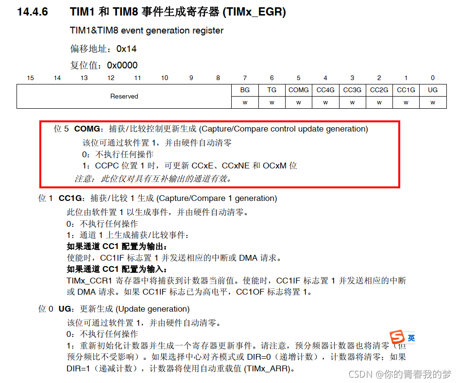
COM The event occurred with 2 In the way : By function TIM_SelectCOM() Choose
- Software TIM_GenerateEvent(TIM8,TIM_EventSource_COM);
- Hardware TRGI Automatic triggering

Hardware TRGI What are the conditions : Look at the picture below

The red box is TRGI The input source , In front of the selector are TRGI The source of the , We can see the relevant registers TIMx_SMCR

On the way of hardware generation COM Please read another article about the incident , I won't go into too much detail here
1. The registers involved are :
TIMx_CR2
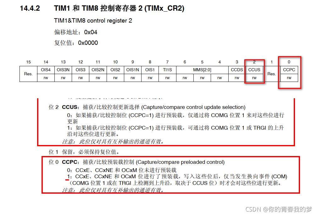
Explain :CCPUS position : Update method selection , General choice CCUS=1, Both software and hardware can be updated

2. See the following table for common commutation methods , Here you can use the feeling HALL Commutation trigger
Commutation table :546231
5: Conducting phase Q3、Q6
4: Conducting phase Q3、Q2
6: Conducting phase Q5、Q2
2: Conducting phase Q5、Q4
3: Conducting phase Q1、Q4
1: Conducting phase Q1、Q6
Design steps
- TIM1/TIM8 Timer initialization , Add the following items than normal initialization
TIM_CCPreloadControl(TIM8,ENABLE);// Enables capture and comparison of preload controls
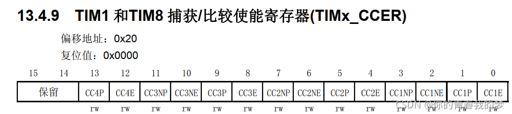
TIM8->CCER&=0x0000;// close 6 road PWM Output or other library functions TIM_CCxCmd() And so on
//COM Interrupt configuration ( It's not necessary )
NVIC_InitStre.NVIC_IRQChannel=TIM8_TRG_COM_TIM14_IRQn;
NVIC_InitStre.NVIC_IRQChannelPreemptionPriority=0x02;
NVIC_InitStre.NVIC_IRQChannelSubPriority=0x01;
NVIC_InitStre.NVIC_IRQChannelCmd=ENABLE;
NVIC_Init(&NVIC_InitStre);// initialization
TIM_ITConfig(TIM8,TIM_IT_COM,ENABLE);// Can make TIM1/8 Of COM Trigger interrupt
2.6 road IO Mouth initialization , Configure advanced timer
3.HALL Timers and IO initialization
4.HALL The input capture interrupt service function is written
5.COM Write the interrupt service function triggered by the event ( Don't )
Here is only the design idea and algorithm process , Detailed about BLDC Please refer to other materials for the algorithm design
HALL Input capture interrupt service function , Complete the function :
according to hall Read the value to judge the commutation sequence , In the corresponding commutation , to update 3 Road duty cycle ( It hasn't come into effect yet )
Switch(ReadHallVal)
{
Case 5: to update 3 Road duty cycle ;TIM8->CCER=SetVal_DISABLE_ENABLE; break;
Case 4: to update 3 Road duty cycle ;TIM8->CCER= SetVal_DISABLE_ENABLE; break;
Case 3: to update 3 Road duty cycle ;TIM8->CCER= SetVal_DISABLE_ENABLE; break;
Case 2: to update 3 Road duty cycle ;TIM8->CCER= SetVal_DISABLE_ENABLE; break;
Case 6: to update 3 Road duty cycle ;TIM8->CCER= SetVal_DISABLE_ENABLE; break;
Case 1: to update 3 Road duty cycle ;TIM8->CCER= SetVal_DISABLE_ENABLE; break;
}
Update duty cycle available TIMx_CCRx=Num; Or functions TIM_SetCompare1() etc.
SetVal_DISABLE_ENABLE The value is the corresponding selection channel , See... For details TIM8->CCER register , Is to configure the relevant channel to enable or disable
TIM_GenerateEvent(TIM8,TIM_EventSource_COM);// complete COM The emergence of events , The set duty cycle really takes effect , Of course, the effect can also be automatically generated by hardware (TRGI)
This will trigger TIM8 Of COM The interruption of the event ( If the configuration is interrupted ), Interruptions may or may not , If there is no corresponding task to deal with , Can not add
//TIM8 COM Event triggered experiment , Interrupt service function
void TIM8_TRG_COM_TIM14_IRQHandler(void)
{
//LED Level flip , For comparison
}
Demo code : We use software to produce COM Event to update the duty cycle
3. For complementary channels PWM Output , Timer TIM8
#define CH1_ON_CH23_OFF (0x0444|(0x001<<0)) //CH1 open CH2 Turn off CH3 Turn off
#define CH2_ON_CH13_OFF (0x0444|(0x001<<4)) //CH1 Turn off CH2 open CH3 Turn off
#define CH3_ON_CH12_OFF (0x0444|(0x001<<8)) //CH1 Turn off CH2 Turn off CH3 open
//IO Mouth initialization
GPIO_InitTypeDef GPIO_InitStre;
RCC_AHB1PeriphClockLPModeCmd(RCC_AHB1Periph_GPIOA|RCC_AHB1Periph_GPIOB|RCC_AHB1Periph_GPIOC, ENABLE);
GPIO_InitStre.GPIO_Pin=GPIO_Pin_6|GPIO_Pin_7|GPIO_Pin_8;
GPIO_InitStre.GPIO_Mode=GPIO_Mode_AF;
GPIO_InitStre.GPIO_OType=GPIO_OType_PP;
GPIO_InitStre.GPIO_PuPd=GPIO_PuPd_DOWN;
GPIO_InitStre.GPIO_Speed=GPIO_Speed_2MHz;
GPIO_Init(GPIOC, &GPIO_InitStre);
GPIO_InitStre.GPIO_Pin=GPIO_Pin_14|GPIO_Pin_15;
GPIO_InitStre.GPIO_Mode=GPIO_Mode_AF;
GPIO_InitStre.GPIO_OType=GPIO_OType_PP;
GPIO_InitStre.GPIO_PuPd=GPIO_PuPd_NOPULL;
GPIO_InitStre.GPIO_Speed=GPIO_Speed_2MHz;
GPIO_Init(GPIOB, &GPIO_InitStre);
GPIO_InitStre.GPIO_Pin=GPIO_Pin_7;
GPIO_InitStre.GPIO_Mode=GPIO_Mode_AF;
GPIO_InitStre.GPIO_OType=GPIO_OType_PP;
GPIO_InitStre.GPIO_PuPd=GPIO_PuPd_NOPULL;
GPIO_InitStre.GPIO_Speed=GPIO_Speed_2MHz;
GPIO_Init(GPIOA, &GPIO_InitStre);
/* Connect TIM3 pins to AF2 */
GPIO_PinAFConfig(GPIOC, GPIO_PinSource6, GPIO_AF_TIM8);
GPIO_PinAFConfig(GPIOC, GPIO_PinSource7, GPIO_AF_TIM8);
GPIO_PinAFConfig(GPIOC, GPIO_PinSource8, GPIO_AF_TIM8);
GPIO_PinAFConfig(GPIOA, GPIO_PinSource7, GPIO_AF_TIM8);
GPIO_PinAFConfig(GPIOB, GPIO_PinSource14, GPIO_AF_TIM8);
GPIO_PinAFConfig(GPIOB, GPIO_PinSource15, GPIO_AF_TIM8);
TIM_TimeBaseInitTypeDef TIM_TimeBaseInitStre;
TIM_OCInitTypeDef TIM_OCInitStre;
TIM_BDTRInitTypeDef TIM_BDTRInitStructure;
// Timer initialization
RCC_APB2PeriphClockCmd(RCC_APB2Periph_TIM8, ENABLE);
PV_PEEP_IO_Init();//IO Mouth initialization
// Counting frequency 20kHz=168/(TIM_Prescaler+1)/(TIM_Period+1)
TIM_TimeBaseInitStre.TIM_Prescaler=100-1;// Timer frequency 168M/(0+1)
TIM_TimeBaseInitStre.TIM_Period=11200-1;// Cycle count value 15k-11200 A count value Change to 20kHz-8400
TIM_TimeBaseInitStre.TIM_ClockDivision=0x00;// Regardless of the frequency
TIM_TimeBaseInitStre.TIM_CounterMode=TIM_CounterMode_CenterAligned1 ;
TIM_TimeBaseInitStre.TIM_RepetitionCounter=0x00;
TIM_TimeBaseInit(TIM8, &TIM_TimeBaseInitStre);
TIM_OCInitStre.TIM_OCMode=TIM_OCMode_PWM1;
TIM_OCInitStre.TIM_OCPolarity=TIM_OCPolarity_High ;
TIM_OCInitStre.TIM_OCIdleState=TIM_OCIdleState_Reset ;
TIM_OCInitStre.TIM_OutputState=TIM_OutputState_Enable;
TIM_OCInitStre.TIM_OCNPolarity=TIM_OCPolarity_High;
TIM_OCInitStre.TIM_OCNIdleState=TIM_OCIdleState_Reset;
TIM_OCInitStre.TIM_OutputNState=TIM_OutputState_Enable ;
TIM_OCInitStre.TIM_Pulse=0;// Duty cycle 0%
TIM_OC1Init(TIM8, &TIM_OCInitStre);// Silencing coil
TIM_OCInitStre.TIM_Pulse=0;// Duty cycle 0%
TIM_OC2Init(TIM8, &TIM_OCInitStre);// Silencing coil
TIM_OCInitStre.TIM_Pulse=0;// Duty cycle 0%
TIM_OC3Init(TIM8, &TIM_OCInitStre);// Silencing coil
TIM_BDTRInitStructure.TIM_OSSRState = TIM_OSSRState_Enable;
TIM_BDTRInitStructure.TIM_OSSIState = TIM_OSSIState_Enable;
TIM_BDTRInitStructure.TIM_LOCKLevel = TIM_LOCKLevel_1;
TIM_BDTRInitStructure.TIM_DeadTime = 132;//
TIM_BDTRInitStructure.TIM_AutomaticOutput = TIM_AutomaticOutput_Disable;
TIM_BDTRConfig(TIM8, &TIM_BDTRInitStructure);
TIM_OC1PreloadConfig(TIM8, TIM_OCPreload_Enable);
TIM_OC2PreloadConfig(TIM8, TIM_OCPreload_Enable);
TIM_OC3PreloadConfig(TIM8, TIM_OCPreload_Enable);
TIM_CtrlPWMOutputs(TIM8, ENABLE);// Advanced timer needs to be enabled with this
TIM_Cmd(TIM8, ENABLE);// Can make the clock
TIM_GenerateEvent(TIM8, TIM_EventSource_Update);
TIM8->CCER = 0x0444;// Disability 3 Output to channel PWM
Here, the serial port is used to interrupt the reception of data , To simulate the 6 Step commutation
void USART1_IRQHandler( void )// A serial port 1 interrupt
{
u8 CHannel = 0;
// receive
if( USART_GetITStatus( USART1, USART_IT_RXNE ) != RESET )
{
CHannel = USART_ReceiveData( USART1 );
}
switch(CHannel)
{
Case1:TIM8->CCR1=5000;TIM8->CCR2=0;TIM8->CCR3=0;TIM8->CCER=CH2_ON_CH13_OFF; TIM_GenerateEvent(TIM8, TIM_EventSource_Update);break;//TIM8->CCER=0x0445
case2:TIM8->CCR1=0;TIM8->CCR2=5000;TIM8->CCR3=0;TIM8->CCER=CH2_ON_CH13_OFF; TIM_GenerateEvent(TIM8, TIM_EventSource_Update);break;
case3:TIM8->CCR1=0;TIM8->CCR2=0;TIM8->CCR3=5000;TIM8->CCER=CH3_ON_CH12_OFF; TIM_GenerateEvent(TIM8, TIM_EventSource_Update);break;
default:;break;
}
TIM_GenerateEvent(TIM8,TIM_EventSource_COM);// produce COM event
}
Why add TIM_GenerateEvent(TIM8, TIM_EventSource_Update); To clear the counter 0, namely TIM8->CNT=0
Experimental phenomena :
PWM Output channel start duty cycle =0, An event generated by the external serial port triggers the duty cycle update of the corresponding channel , Count ; Duty cycle = The set value , The oscillograph waveform is as follows
chart 1 Is the hardware automatically updates the duty cycle comparison value , It can be seen that there is a significant delay between channel switching

chart 1
chart 2 It's software COM Event to update the duty cycle comparison value , Channel switching has little delay

chart 2
版权声明
本文为[Your youth my dream]所创,转载请带上原文链接,感谢
https://yzsam.com/2022/04/202204220603472415.html
边栏推荐
- 集合之List接口
- Visual programming - drawing assignment
- ThreadLocal test multithreaded variable instance
- 批量下載文件----壓縮後再下載
- If statement format flow
- The art of concurrent programming (3): an in-depth understanding of the principle of synchronized
- 2022 团体程序设计天梯赛 模拟赛 L2-1 盲盒包装流水线 (25 分)
- 变量、常量、运算符
- SQL learning record
- 浅学一下I/O流和File类文件操作
猜你喜欢
Build websocket server in. Net5 webapi

7-1 introduction to finance
Database - MySQL -- Navicat import SQL error 1067 - invalid default value for 'paydate‘

Use of rotary selector wheelpicker

2022 团体程序设计天梯赛 模拟赛 L2-4 哲哲打游戏 (25 分)
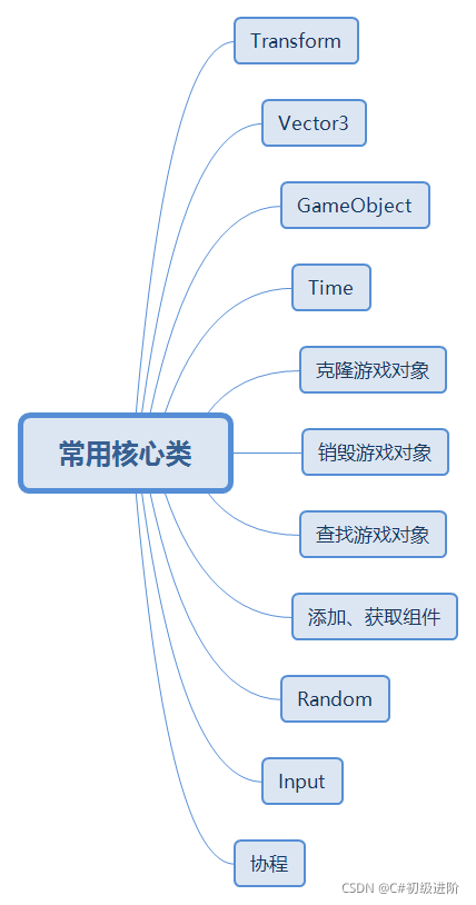
Unity knowledge points (common core classes)

Explanation keyword of MySQL
![Super easy to use [general excel import function]](/img/9b/ef18d1b92848976b5a141af5f239b5.jpg)
Super easy to use [general excel import function]

File upload vulnerability summary and upload labs shooting range documentary
MySQL zip installation tutorial
随机推荐
C-10 program error correction (recursive function): number to character
Learn about I / O flow and file operations
JS takes out the same elements in two arrays
Téléchargement en vrac de fichiers - téléchargement après compression
The content of the website is prohibited from copying, pasting and saving as JS code
Database SQL -- simulate inserting a large amount of data, importing / exporting database scripts, timestamp conversion and database basics
Laboratory safety examination
Software testing process
Three types of cyclic structure
When migrating tslib_ setup: No such file or directory、ts_ open: No such file or director
Idempotency practice operation, explaining idempotency based on business
Supersocket is Use in net5 - concept
Section 1 array and slicing in Chapter 6
Problem B: small challenge
打卡:4.23 C语言篇 -(1)初识C语言 - (12)结构体
批量下载文件----压缩后再下载
Unity Basics
Variable definition and use
Problem C: realize Joseph Ring with linked list
淺學一下I/O流和File類文件操作