当前位置:网站首页>PWM output of STM32 to steering gear sg90
PWM output of STM32 to steering gear sg90
2022-04-22 08:20:00 【Wozart_ Kate】
PWM The implementation of the
Hardware basis of single chip microcomputer and its counting principle
Universal timer


Add up the count ( Count up )

Alternate counting

PWM Duty cycle setting
pwm.c
#include "pwm.h"
void TIM3_PWM_Init(u16 arr,u16 psc){
//TIM3 PWM initialization arr Reload value psc The prescaled coefficients
GPIO_InitTypeDef GPIO_InitStrue;
TIM_OCInitTypeDef TIM_OCInitStrue;
TIM_TimeBaseInitTypeDef TIM_TimeBaseInitStrue;
// Turn on the timers separately ,GPIO Clock with multiplex interface
RCC_APB1PeriphClockCmd(RCC_APB1Periph_TIM3,ENABLE);// Can make TIM3 And the related GPIO The clock
RCC_APB2PeriphClockCmd(RCC_APB2Periph_GPIOB,ENABLE);// Can make GPIOB The clock (LED stay PB0 Pin )
RCC_APB2PeriphClockCmd(RCC_APB2Periph_AFIO,ENABLE);// Can make AFIO The clock ( Timer 3 passageway 3 Need to remap to BP5 Pin )
GPIO_InitStrue.GPIO_Pin=GPIO_Pin_0; // TIM_CH3
GPIO_InitStrue.GPIO_Mode=GPIO_Mode_AF_PP; // Reuse push pull
GPIO_InitStrue.GPIO_Speed=GPIO_Speed_50MHz; // Set the maximum output speed
GPIO_Init(GPIOB,&GPIO_InitStrue); //GPIO Port initialization settings
// GPIO_PinRemapConfig(GPIO_PartialRemap_TIM3,ENABLE); // mapping , Remapping is only used for 64、100、144 Single chip microcomputer foot
// Remapping of reuse function generally refers to
// “ When the corresponding pin is occupied , By setting remap RemapConfig To change the timer ( Or other equipment ) The value corresponding to the pin used ”
// When there is no remapping ,TIM3 The four channels of CH1,CH2,CH3,CH4 They correspond to each other PA6,PA7,PB0,PB1
// When partially remapped ,TIM3 The four channels of CH1,CH2,CH3,CH4 They correspond to each other PB4,PB5,PB0,PB1 (GPIO_PartialRemap_TIM3)
// When completely remapped ,TIM3 The four channels of CH1,CH2,CH3,CH4 They correspond to each other PC6,PC7,PC8,PC9 (GPIO_FullRemap_TIM3)
TIM_TimeBaseInitStrue.TIM_Period=arr; // Set auto reload load value ( Count overflow value )
TIM_TimeBaseInitStrue.TIM_Prescaler=psc; // The prescaled coefficients ( Number of cycles of one frequency )
TIM_TimeBaseInitStrue.TIM_CounterMode=TIM_CounterMode_Up; // The counter overflows up
// #define TIM_CounterMode_Up ((uint16_t)0x0000) Add up the count
// #define TIM_CounterMode_Down ((uint16_t)0x0010) Down / Decrement count
// #define TIM_CounterMode_CenterAligned1 ((uint16_t)0x0020) Alternate counting , And in ARR Overflow at
// #define TIM_CounterMode_CenterAligned2 ((uint16_t)0x0040) Alternate counting , And in CNT=0 Overflow at
// #define TIM_CounterMode_CenterAligned3 ((uint16_t)0x0060) Alternate counting , And in ARR and CNT=0 Overflow at
TIM_TimeBaseInitStrue.TIM_ClockDivision=TIM_CKD_DIV1; // The division factor of the clock , It plays a little delay role , General set to TIM_CKD_DIV1( Unstable use TIM_CKD_DIV2)
TIM_TimeBaseInit(TIM3,&TIM_TimeBaseInitStrue); //TIM3 Initialize settings ( Set up PWM The cycle of )
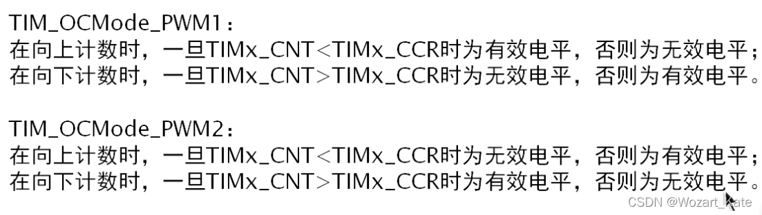
TIM_OCInitStrue.TIM_OCMode=TIM_OCMode_PWM1; // PWM Pattern 1:CNT < CCR Output effective level at
// #define TIM_OCMode_Timing ((uint16_t)0x0000)
// #define TIM_OCMode_Active ((uint16_t)0x0010)
// #define TIM_OCMode_Inactive ((uint16_t)0x0020)
// #define TIM_OCMode_Toggle ((uint16_t)0x0030)
// #define TIM_OCMode_PWM1 ((uint16_t)0x0060)
// #define TIM_OCMode_PWM2 ((uint16_t)0x0070)
TIM_OCInitStrue.TIM_OCPolarity=TIM_OCPolarity_High;// Set polarity - The effective level is : High level
TIM_OCInitStrue.TIM_OutputState=TIM_OutputState_Enable;// Output enable
TIM_OC3Init(TIM3,&TIM_OCInitStrue); //TIM3 The passage of 3 PWM Mode setting
TIM_OC3PreloadConfig(TIM3,TIM_OCPreload_Enable); // Enable preload register
TIM_Cmd(TIM3,ENABLE); // Can make TIM3
}
 Set the clock
 Set interface
 The loading value in the structure , Frequency division coefficient and counting mode loading function
 Set high / Low level active
 Enable register and clock
main.c Realize to SG90 The control of
int main (void){
    // The main program
	delay_ms(500); // Wait for other devices to be ready when powered on
	RCC_Configuration(); // System clock initialization
	RELAY_Init();// Relay initialization

	I2C_Configuration();//I2C initialization
	OLED0561_Init(); //OLED initialization
	OLED_DISPLAY_8x16_BUFFER(0," YoungTalk "); // display string
	OLED_DISPLAY_8x16_BUFFER(3," SG90 TEST2 "); // display string

	TOUCH_KEY_Init();// Key initialization
	TIM3_PWM_Init(59999,23); // Set the frequency to 50Hz, Formula for : Overflow time Tout( Unit second )=(arr+1)(psc+1)/Tclk 20MS = (59999+1)*(23+1)/72000000
                          //Tclk Clock for general timer , If APB1 There is no frequency division , Then it is the system clock ,72MHZ
                          //PWM clock frequency =72000000/(59999+1)*(23+1) = 50HZ (20ms), Set the auto load value 60000, The prescaled coefficients 24

	while(1){

		if(!GPIO_ReadInputDataBit(TOUCH_KEYPORT,TOUCH_KEY_A)){
     // Read the level of the touch button
			OLED_DISPLAY_8x16_BUFFER(6," Angle 0 "); // display string
			TIM_SetCompare3(TIM3,1500);        // Change the comparison value TIM3->CCR2 Achieve the effect of adjusting the duty cycle (1500 by 0 degree )
			//void TIM_SetCompare3(TIM_TypeDef* TIMx, uint16_t Compare3) By setting Compare3 To set the duty cycle

		}
		if(!GPIO_ReadInputDataBit(TOUCH_KEYPORT,TOUCH_KEY_B)){
     // Read the level of the touch button
			OLED_DISPLAY_8x16_BUFFER(6," Angle 45 "); // display string
			TIM_SetCompare3(TIM3,3000);        // Change the comparison value TIM3->CCR2 Achieve the effect of adjusting the duty cycle
		}
		if(!GPIO_ReadInputDataBit(TOUCH_KEYPORT,TOUCH_KEY_C)){
     // Read the level of the touch button
			OLED_DISPLAY_8x16_BUFFER(6," Angle 90 "); // display string
			TIM_SetCompare3(TIM3,4500);        // Change the comparison value TIM3->CCR2 Achieve the effect of adjusting the duty cycle
		}
		if(!GPIO_ReadInputDataBit(TOUCH_KEYPORT,TOUCH_KEY_D)){
     // Read the level of the touch button
			OLED_DISPLAY_8x16_BUFFER(6," Angle 180 "); // display string
			TIM_SetCompare3(TIM3,7500);        // Change the comparison value TIM3->CCR2 Achieve the effect of adjusting the duty cycle
		}
	}
}
版权声明
本文为[Wozart_ Kate]所创,转载请带上原文链接,感谢
https://yzsam.com/2022/04/202204220705214524.html
边栏推荐
- Redis entry required
- 计算机保研面试中,都有哪些令人窒息的问题?
- nacos基础(4):配置nacos外部数据库
- 综合光接入设备提供16路E1业务口4路百兆隔离网络2路千兆隔离以太网光端机
- 铝酸镧LaAlO3晶体基片|硅Si晶体基片|掺铁钛酸锶Fe:SrTiO3晶体基片|掺铌钛酸锶Nb:SrTiO3晶体基片|齐岳供应晶体基片种类丰富
- Leprechaun green elf magic strikes
- SQL 基础(八)数据更新操作实战演练
- pytest_ First class
- Integrated service PDH optical transceiver 4-way Gigabit isolated Ethernet + 4-way E1 private network service 2m integrated service optical transceiver
- 荧光标记的透明质酸|FITC-Hyaluronate|荧光素透明质酸|Fluorescent hyaluronic acid
猜你喜欢

pycharm终端pip安装Error: “pip”项识别为 cmdlet、函数、脚本文件或可运行程序的名称
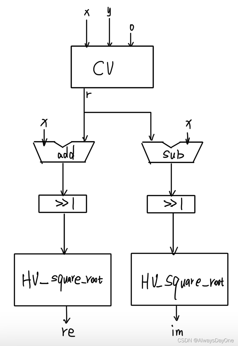
HLS / Chisel 实践CORDIC高性能计算复数平方根

【软件测试】零基础一文看懂软件测试基础知识
金九银十面试季,字节跳动面试题拿走不谢(附详细答案解析)
2022年全国中职组网络安全国赛赛题思路(仅自己一个做题的思路)——网络安全竞赛试题(7)
tf.keras.layers.Conv?D函数
REINFORCE

阻塞队列BlockingQueue

LeetCode_118. 杨辉三角_动态规划_int**的学习

电信级双光口保护8E1+4路物理隔离千兆网络光端机1000M网络100M光端机
随机推荐
Sun Yuchen, founder of wave field Tron, announced that it will officially launch the decentralized stable currency usdd
Variante rapide: trouver le nombre maximum de K premiers
2022. How to use Chengdu 90 minute unlimited studio
tf.keras.layers.Conv?D函数
nacos基础(3):OPEN API配置管理测试与关闭nacos服务
16路E1光端机+4路百兆以太网络光端机PDH光端机2M综合业务光端机
4E1+2路千兆隔离网络+4路百兆物理隔离网络PDH光端机
Architects evaluate the current situation and development prospect of software industry
牛客白月赛5 【题解 数学场】
变种快排:寻找最大的前K个数
Data driven pytest1
提供4路E1业务口4路百兆隔离网络2M E1专网多业务PDH光端机
微信小程序页面路由
MYSQL05_ORDR BY排序、LIMIT分组、GROUP BY分组
电信级双光口保护8E1+4路物理隔离千兆网络光端机1000M网络100M光端机
分布式事物详解
综合业务PDH光端机4路千兆隔离以太网络+4路E1专网业务2M综合业务光端机
软件测试之接口自动化面试题汇总
【欧拉计划第 13 题】 大数之和 Large sum
实验四、数据预处理