当前位置:网站首页>Principle and characteristic analysis of triode
Principle and characteristic analysis of triode
2022-04-23 06:47:00 【tilblackout】
- Before reading this article, please make sure you master PN junction 、 Detailed explanation and application of diode principle The content in
- For the symbol of triode 、PNP and NPN The basic knowledge such as the difference between is not explained here
1 principle
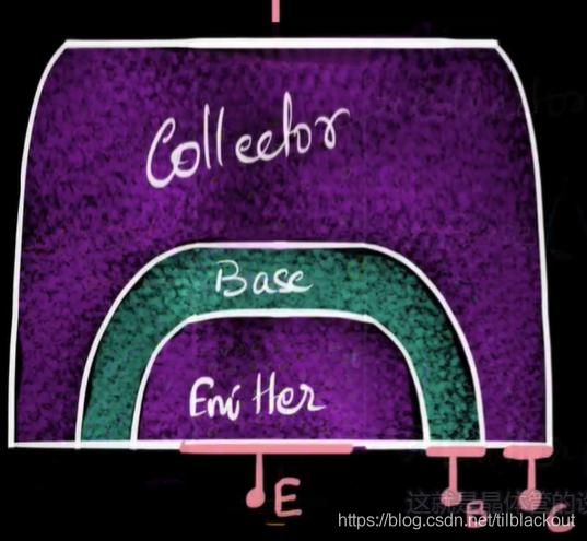
Start with NPN Take triode as an example :

- The collector electrons in the figure should be painted less ( Less doping ), The size should be drawn higher ( Large size , Not easy to heat ), It will be explained later
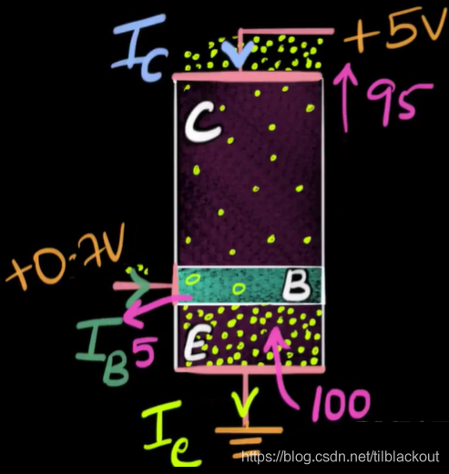
The base and emitter are positively biased , So the electrons from the emitter will spread to the base . Due to collector and base PN The knot is reversed , Its depletion region increases , Direction is N->P The electric field increases . At this time, increasing the voltage is not like doping with normal concentration PN The drift current is almost constant with the increase of voltage , Because the doping of the base is very little and very thin , So the electrons that diffuse to the base have little time to combine with the holes in the base ( Only a few are combined ), Most electrons can easily reach the top and reverse bias PN The internal electric field of the junction enters the collector .
Process manufacturing :
(1) The base : Must be very thin 、 The doping concentration is very low
(2) The emitter : Inject electrons into the base , So it needs a lot of doping
(3) Collector : Strictly speaking , No matter how much the collector is doped , But we don't want to C-B Of PN The junction is broken down , Therefore, it is necessary to ensure a large breakdown voltage . Recall the zener diode , Its doping is high , So the breakdown voltage is small . Now the base doping is very little , So the less doped the collector , The greater the breakdown voltage . Therefore, the doping of collector should be less .
- In some transistors, the doping concentration of collector is between the base and emitter , In some transistors, the collector is less doped than the base , So there are no hard and fast rules
(4) Size : The collector size should be larger than the base , In this way, when the current flows , It won't get hot so easily ; The base is highly doped , So it can't be too big .
So the actual triode may be like this :
2 characteristic
Take the common emitter amplifier as an example
2.1 electric current
The electrons coming out of the base and the electrons coming out of the collector will eventually return to the emitter (B、E、C Finally, they are grounded ), As an injection of electrons . namely IE=IB+IC.
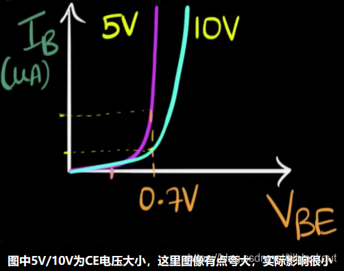
2.2 Input features :IB And UBE
- When UBE<0.7V when ,B and C Very little current
- UBE>0.7V when ,IB a surge , however IB be relative to IC It's still very small .
- If you increase UCE, Above PN The depletion region of the junction increases , be UBE It needs to be bigger ,IB Will start to surge . But this change is small , So you can say UCE No effect UBE Size .
2.3 output characteristic :Ic And UCE
When UC The value of is less than 0.7V when , above PN The knot is positive and partial . The assumption is 0.3V,UBC=0.7-0.3V=0.4V, The width of depletion region decreases ,C Polar electrons may spread to B extremely , and E Polar diffusion to B Polar electrons , It will still spread to C extremely , But it's not as easy as it used to be . So at this time IC Will follow UCE To reduce by .
2.4 Zoom in 、 saturated 、 end
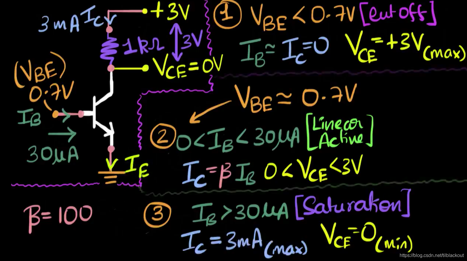
As shown in the figure , Suppose the transistor amplification factor is 100 times ,C Pole connection 3V Then one 1K resistance , here C Maximum current of pole ICmax=3mA.
(1) Cut off zone : When UBE<0.7V Time is up , here IB≈IC=0,C The pole resistance has no voltage drop , therefore UCE To the maximum 3V
(2) Zoom in :UBE≈0.7V And β*IB<ICmax, As mentioned earlier, this pressure drop is almost unaffected by UCE influence , about Si It's usually 0.7V. here ,0V<UCE<3V.
(3) Saturation zone :UBE≈0.7V And β*IB>ICmax, because C The polar current cannot be higher than 3mA, therefore IC Keep at maximum 3mA Can't rise any higher ,UCE=0.
Switch action :
- In the saturation zone ,C Pole current max 、UCE=0, amount to CE Pole short circuit
- When the cut-off zone ,C There is no current at all 、UCE To the maximum , amount to CE Pole open circuit

版权声明
本文为[tilblackout]所创,转载请带上原文链接,感谢
https://yzsam.com/2022/04/202204230549282938.html
边栏推荐
猜你喜欢

C语言的浪漫
js获取链接?后边的参数名称或者值,根据url ?后的参数做判断
![[UDS unified diagnostic service] II. Network layer protocol (1) - overview and functions of network layer](/img/39/30bb897ff4467105de08c8c1c737ab.png)
[UDS unified diagnostic service] II. Network layer protocol (1) - overview and functions of network layer
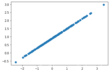
基于TensorFlow的线性回归实例
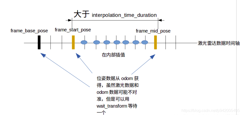
深蓝学院激光slam 理论与实践 第三章激光雷达去畸变 作业习题

欢迎使用Markdown编辑器

【UDS统一诊断服务】一、诊断概述(2)— 主要诊断协议(K线和CAN)
PHP junior programmers, take orders and earn extra money

Installation of GCC, G + +, GDB
【UDS统一诊断服务】四、诊断典型服务(1)— 诊断和通信管理功能单元
随机推荐
信息学一本通-小球
日志写法(带时间)
在MFC中使用printf
约瑟夫序列 线段树 O(nlogn)
WMI技术介绍和应用
Generate shortcut
Installation of GCC, G + +, GDB
ES6面试题(参考文档)
Round up a little detail of the round
Running QT program in visual Stdio
进程管理命令
realsense 选型大对比D455 D435i D415 T265 3D硬件对比
Krypton binary
20220222回归职场
[opencv] use filestorage to read and write eigenvectors
[UDS unified diagnosis service] IV. typical diagnosis service (1) - diagnosis and communication management function unit
C语言进阶要点笔记2
JS高频面试题
QT icon application
_findnext 报错