当前位置:网站首页>STM32 learning note 2 - set GPIO register to realize running water lamp
STM32 learning note 2 - set GPIO register to realize running water lamp
2022-04-22 06:05:00 【Lithium salt block】
STM32 Learning notes 2—— Set up GPIO Register to achieve water lamp
Write it at the front
Before learning , Predecessors always told me to master registers , Yesterday was the first day to officially start studying the board , It starts with library functions , Although I can understand what I'm doing , Always feel like something's missing . Today, my classmate asked me whether you implemented it with library function or configuration register . So I began to study the configuration of registers .
One 、 To configure GPIO register
GPIO The configuration is similar to yesterday's process , Just don't call library functions , Directly related to the setting of the register .
Or yesterday's schematic diagram :
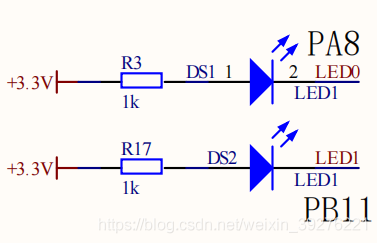
Or settings PA8 Take an example to illustrate .
1. Can make IO Port clock
The first step in using library functions is to define a GPIO Structural variable , If you configure the register directly, you don't need to define a GPIO Structure variable to assign value , Just assign a value to the register directly . So the first step is to enable the corresponding IO The clock of the port .
// Library function
RCC_APB2PeriphClockCmd(RCC_APB2Periph_GPIOA,ENABLE);
Can make IO Port clock , According to yesterday's experience, it should be in RCC Then find the register . Register found , Set according to the data manual OK.


therefore
// register
RCC->APB2ENR |= (1 << 2);//ENABLE GPIOA CLK
2. To configure PA8 Corresponding parameters of the pin
If you understand it by the small steps subdivided when learning library functions yesterday , All three members of the structure are finished in this step . To set up PA8 Pin , First find the register that controls it .


To set up for 50M Push pull output mode , Therefore, the register is no 3 Position to the first 0 Is it 0011, That is to say 0x03.
However, it should be noted that when setting the control register , You have to clear it first .
GPIOA->CRH &= 0xFFFFFFF0;//CLEAR PA8
GPIOA->CRH |= 0x00000003;//PA8 50M PP
It can be said that the initialization has been completed now .
Just configure other pins like this .
Two 、 Realization of water lamp
1.LED Pin configuration
LED.h
#ifndef __LED_H
#define __LED_H

void LED_GPIO_Config(void);

#endif /* __LED_H */
LED.c
#include "LED.h"


void LED_GPIO_Config(void)
{

	//PA8
	RCC->APB2ENR |= (1 << 2);//enable GPIOA CLK
	GPIOA->CRH &= 0xFFFFFFF0;//clear PA8
	GPIOA->CRH |= 0x00000003;//PA8 50M PP
	GPIOA->ODR |= 1<<8;//LED0_OFF

	//PB11
	RCC->APB2ENR |= (1 << 3);//enable GPIOB CLK
	GPIOB->CRH &= 0xFFFF0FFF;//clear PB11
	GPIOB->CRH |= 0x00003000;//PB11 50M PP
	GPIOB->ODR |= 1<<11;//LED1_OFF

}
2. The main function
#include "stm32f10x.h"
#include "LED.h"
#include "DELAY.h"

int main(void)
{

	LED_GPIO_Config();

	while(1)
	{

		GPIOA->ODR |=(1<<8);
		GPIOB->ODR &=~(1<<11);
		Delay(0x2fffff);

		GPIOA->ODR &=~(1<<8);
		GPIOB->ODR |=(1<<11);
		Delay(0x2fffff);
	}
}
summary
Today, I always want to control from the key LED The lamp starts to master the setting of the register , Overestimate your mastery of registers , So that when the running program can't run normally, I don't know where to check , Because there are so many problems . Finally, just configure it honestly LED The lights start , Slowly master one by one and then correct mistakes , Finally, a water lamp came out , It's a little harvest . Write notes before today's study , The register configuration version of the program that still struggles to add keys , The result is to hit yourself more . That's it today , Go on learning tomorrow , Take your time , After all, it's just chicken , How high can you expect of yourself .
版权声明
本文为[Lithium salt block]所创,转载请带上原文链接,感谢
https://yzsam.com/2022/04/202204220539557124.html
边栏推荐
- Chapter 88 leetcode sword refers to offer dynamic programming (V) maximum value of gifts
- AIX6.1编译openssl
- IWDG
- Blue Bridge Cup Sprint - binary enumeration
- 由浅入深:小白爬虫学习之旅(1)
- MYSQL知识点总结大全
- Chapter 86 leetcode refers to offer dynamic programming (III) maximum profit of stock
- c语言开发postgres自定义函数
- Error in QT: undefined reference to ` widget:: settime()‘
- Blue Bridge Cup 31 day sprint day23
猜你喜欢


随机推荐
Installation of QT learning
pykmip测试
软件测试分类
Dlopen calls dynamic library
日常学习记录——读取自定义数据集
pygame 简单的飞机大战
Compiling OpenSSL on HP UNIX and using
第88篇 LeetCode剑指Offer动态规划(五)礼物的最大值
Blue Bridge Cup embedded expansion board learning nixie tube
Standard input, standard output, standard error redirection and pipeline
蓝桥杯嵌入式学习之双路AD采集
11 - process control - for loop
蓝桥杯嵌入式扩展板学习之LIS302DL
ADC
Blue Bridge Cup 31 day sprint day14
LeetCode 898. Subarray bitwise OR operation - set
stm32单片机与LD3320语音模块交互法二
由浅入深:小白爬虫学习之旅(1)
QT中出现error: undefined reference to `Widget::SetTime()‘
Part 75 leetcode exercise (8) 8 String to integer