当前位置:网站首页>Design of second-order RC low-pass filter for PWM wave to DC
Design of second-order RC low-pass filter for PWM wave to DC
2022-04-22 07:08:00 【Your youth my dream】
1. Principle and Application
(1) The principle is directly quoted * atom STM32 Explain PWM turn DAC Chapter *


(2) When MCU in DAC When the function is not enough , But also output controllable DC level , This mode can be used to achieve the purpose ; Others are made up of PWM Controlled load device , Such as proportional valve 、 The motor , To test the equivalent current flowing through these loads , You can also use this method
2. Demand analysis
We use second order here RC Low pass filtering to achieve the purpose of current detection resistance PWM Wave equivalent DC DC level function ;
The circuit diagram is as follows , there PWM No MCU Direct output , But the signal processed by the push-pull amplifier circuit

R11/R12 、C3/C4 Form a second order RC wave filtering ; here R11=R12、C3=C4
3. Mathematical calculation
If we require the result of filtering to reach the detection current ±1mA, be 1 The accuracy of one bit reaches 1.5/2048=0.0007324V, Sampling resistance level range 0-1.5V
Assume the filtered signal voltage range 0-1.5V, Then the maximum value of the first harmonic 1.5*2/π=0.95496, Then the circuit should at least provide -20log(0.95496/0.0007324V)=-63dB attenuation
the PWM yes F=20KHz
If it's first order RC wave filtering , The cut-off frequency Fs Is calculated by -10*log[1+(F/Fs)^2]=-63dB, have to Fs=14Hz
If it's second order RC wave filtering , The cut-off frequency Fs Is calculated by -20*log[1+(F/Fs)^2]=-63dB, have to Fs=532Hz
Parameters RC choice :
A second-order low-pass filter is used here ,Fs=1/2πRC, have to R=1KΩ,C=300nF( Here is the designer's choice ),(R11=R12=R,C3=C4=C), This RC The product is a constant value , as for R C Select combination , It can be determined according to practical application , But there is an idea :R or C Not too small , such as R When it's big ,C Must be smaller , At this time, due to the parasitic effect of the circuit , Resulting in a large proportion of the final equivalent capacitance increase , It will affect the filtering effect , That won't work ; Choose... In reverse R equally
First order and second-order comparison , Except for the difference in circuit ; The calculated cut-off frequency is also very different
The second-order attenuation is a little more serious than the first-order attenuation 、 But the second-order delay is small , And the first-order ripple is large

4. Circuit simulation and waveform data - Second order filter
Because the actual load operating current range :0-1A, Therefore, the voltage range on the current resistance 0-1.5V
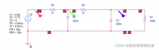
Parameter description : Use here Cadence OrCAD Circuit simulation function
V1 Is the minimum output level
V2 Is the maximum output level , Actually V1-V2 Choose between to test
TD yes PWM Wave delay time
TR Is the edge rise time
TF Is the edge descent time
PW Duty cycle
PER cycle

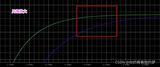
It can be seen from the figure that the green waveform is t=3-4ms Reach stability when , Maximum 3-4ms Delay of ( according to 100% Calculation )
Actually RC Parameter determination , According to the delay time of the output 、 Considering the ripple size ; Of course, this is just a simulation , Into the actual hardware circuit , You will find that there are still changes
In the simulation waveform , You will find that the filtered waveform will attenuate , This needs to be compensated
5. Hardware experiment waveform and data
Finally, select the parameters R=1kΩ、C=220nF The waveforms measured by the actual hardware are as follows :

The simulation results are as follows :

Compare the waveform , The simulation is basically consistent with the actual hardware test
版权声明
本文为[Your youth my dream]所创,转载请带上原文链接,感谢
https://yzsam.com/2022/04/202204220603472600.html
边栏推荐
- [review of Blue Bridge Cup] tree of life
- 集成电路模拟版图入门-版图基础学习笔记(二)
- Application of can optical fiber optical transceiver in photoelectric slip ring
- STM32WB55 蓝牙协议栈运行流程解析
- CAN总线中继网桥在新能源测试系统中的应用。
- Qinheng ch573 development board
- 微电子专业是做芯片的吗?芯片和什么专业有关?
- 芯片设计怎样准备即将面临的秋季补招和来年的春招?
- STM32 learning record 0003 -- Interpretation of STM32 chip
- Introduction to basic terms of machine learning
猜你喜欢

Application of can optical transceiver in fire networking
CAN光纤光端机在光电滑环中的应用

Sss1700 qfn36 single chip designs a USB typec headset | supports the automatic switching of USB headset scheme between wire control and European and American regulations
The test posture should be rigorous
Audio type 523 + VGA + 5 + HDC to 5 + VGA

Dcoker installation

Replace Fe1 1s, ma8601, cost-effective, Chinese solution, Qiyan primary agent, Hub solution

Stm32wb55 RTT based ble sample making process

消防设备光纤联网CAN转光纤转换器

STM32 learning record - development environment installation
随机推荐
MCS-5 中断技术(实践)
疫情环境下工程机械中的透传云网关远程程序升级方案
STM32学习记录0004——ISP串口下载
SSS1700
Ma8608 Qiyan USB 2.0 High Speed 4-port USB hub controller chip scheme
LwIP 1.4.1 Chinese annotation source code
Application of CAN bus relay bridge in new energy test system.
Cs5202 chip specification 𞓜 cs5202 replaces cs5212 | HDMI to VGA chip
Have you really done the right way to add stamp holes on PCB
在消防联网(楼宇、工厂、海上风电、管廊等)中CAN光纤转换器、CAN总线光端机典型应用案例
替代 FE1.1s HUB读卡主控芯片-MA8601
STM32学习记录0002-STM32初探
统计2015-2017年间911中的类别
STM32 learning record 0003 -- Interpretation of STM32 chip
Lcfnet series can to optical fiber Ethernet equipment realizes ultra long-distance optical fiber communication between can networks
Typec转HDMI 4K30HZ扩展芯片方案CS5261和CS5266设计参数及电路对比
Dcoker安装
It's nothing to be able to dismantle the host. Mr. expressway can also test it
MA8608奇岩USB 2.0高速4端口USB HUB集线器控制器芯片方案
rt-thread 移植BSP驱动 uart篇