当前位置:网站首页>Use stm32cube MX / stm32cube ide to generate FatFs code and operate SPI flash
Use stm32cube MX / stm32cube ide to generate FatFs code and operate SPI flash
2022-04-23 18:23:00 【Things will turn when they reach the extreme 1024】
Put my source code here , You can try it first and then make your own changes
https://download.csdn.net/download/qq_27620407/85177326
No points to contact directly [email protected]
1、 Get ready
Single chip microcomputer STM32F103Zet6
flash SPI agreement W25Q32
connection :SPI1 PA567 PA4-CS
2、 effect
SCM can be used fatfs File system access off chip flash
3、 SCM configuration
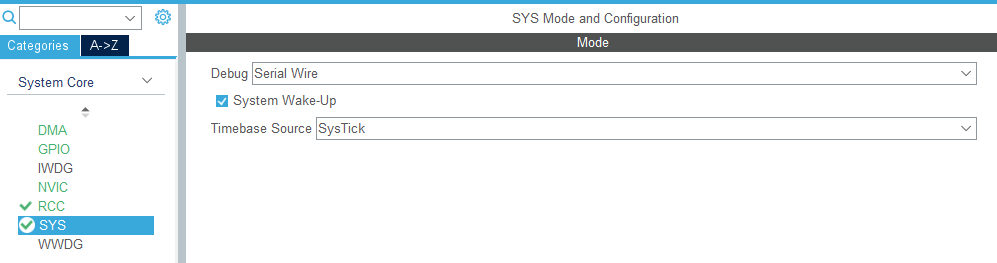
3、1 SYS SWD Simulation
3.2RCC
Because I have RTC The clock , So both clocks are connected

3.3 SPI
I'm useless here cubeMX Match it out , With atomic , Stick it on the back
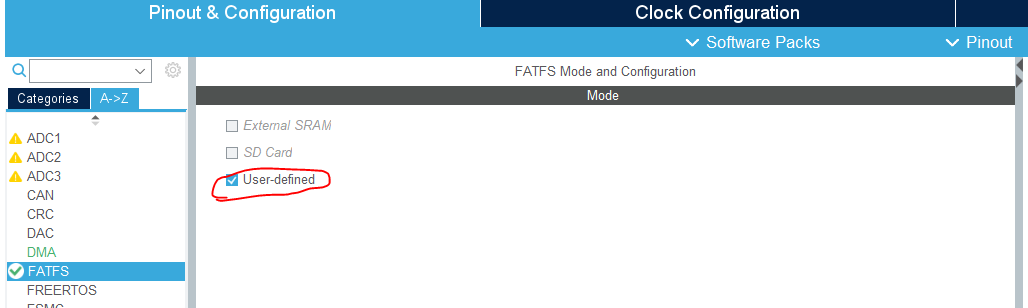
3.4 FATFS
choice user
Next is configuration
You can't choose the version Just this one , Don't worry about anything else

Other configuration
CODE_PAGE Choose Chinese , This can support Chinese paths
USE_LFN Choose this It seems to be a long path , It doesn't work without me
STRF_ENCODE Don't choose anything else , Otherwise, there will be problems with the data type
VOLUMES Is the amount of memory you want to mount , If you don't flash If there's anything else, just change it to 2 3 Other numbers , I have just one
MAX_SS MIN_SS This and flash Related to the sector of , My sector is 4K That is to say 4096 Why don't you move , It's easy for others to use

There's another thing I've been talking about
CubeMX That's all
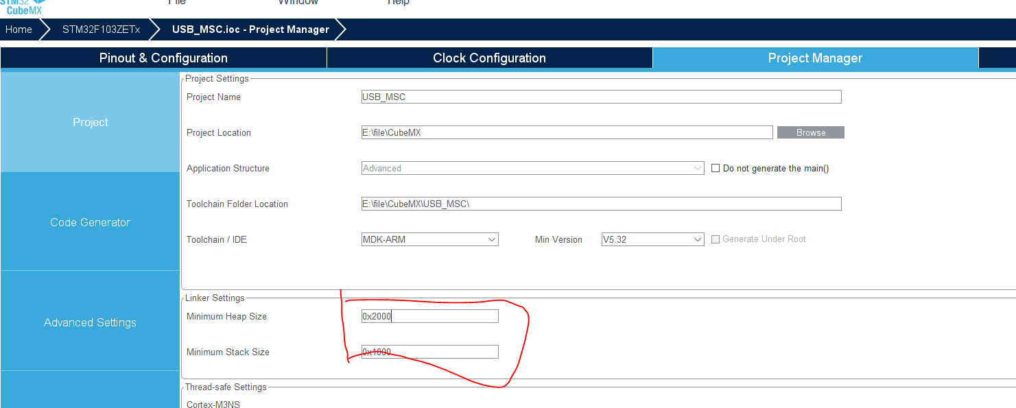
4 Hal Custom code

This is new fatfs Related to the source code , What needs to be changed is user_diskio.c When this document fatfs Interface between file system and hardware ,
Functions that need to add interfaces :
USER_initialize initialization
USER_status Like a query to see if it's busy , No dice , I didn't experiment. It's no use
USER_read Read
USER_write write in
USER_ioctl IO control I copied this function , I don't know what to do with it
I directly pasted the changed source code
Be careful !! Read and write functions fatfs The parameters provided are slice !!! It's not a word !!!!!
user_diskio.c
DSTATUS USER_initialize (
	BYTE pdrv           /* Physical drive nmuber to identify the drive */
)
{

  /* USER CODE BEGIN INIT */
	W25QXX_Init();  //FLASH initialization
    return RES_OK;
  /* USER CODE END INIT */
}

/** * @brief Gets Disk Status * @param pdrv: Physical drive number (0..) * @retval DSTATUS: Operation status */
DSTATUS USER_status (
	BYTE pdrv       /* Physical drive number to identify the drive */
)
{

  /* USER CODE BEGIN STATUS */
	Stat=W25QXX_ReadSR();              // No dice , Can not add
    return RES_OK;
  /* USER CODE END STATUS */
}

/** * @brief Reads Sector(s) * @param pdrv: Physical drive number (0..) * @param *buff: Data buffer to store read data * @param sector: Sector address (LBA) * @param count: Number of sectors to read (1..128) * @retval DRESULT: Operation result */
DRESULT USER_read (
	BYTE pdrv,      /* Physical drive nmuber to identify the drive */
	BYTE *buff,     /* Data buffer to store read data */
	DWORD sector,   /* Sector address in LBA */
	UINT count      /* Number of sectors to read */
)
{

  /* USER CODE BEGIN READ */
  #define FLASH_SECTOR_SIZE 512 // This macro definition is actually placed in flash In our program , Here's just the source , Should be and flash of , Sector bar
			for(;count>0;count--)
			{

				W25QXX_Read(buff,sector*FLASH_SECTOR_SIZE,FLASH_SECTOR_SIZE);
				sector++;
				buff+=FLASH_SECTOR_SIZE;
			}
    return RES_OK;
  /* USER CODE END READ */
}

/** * @brief Writes Sector(s) * @param pdrv: Physical drive number (0..) * @param *buff: Data to be written * @param sector: Sector address (LBA) * @param count: Number of sectors to write (1..128) * @retval DRESULT: Operation result */
#if _USE_WRITE == 1
DRESULT USER_write (
	BYTE pdrv,          /* Physical drive nmuber to identify the drive */
	const BYTE *buff,   /* Data to be written */
	DWORD sector,       /* Sector address in LBA */
	UINT count          /* Number of sectors to write */
)
{

  /* USER CODE BEGIN WRITE */

			for(;count>0;count--)
			{

				W25QXX_Write(buff,sector*FLASH_SECTOR_SIZE,FLASH_SECTOR_SIZE);
				sector++;
				buff+=FLASH_SECTOR_SIZE;
			}
  /* USER CODE HERE */
    return RES_OK;
  /* USER CODE END WRITE */
}
#endif /* _USE_WRITE == 1 */

/** * @brief I/O control operation * @param pdrv: Physical drive number (0..) * @param cmd: Control code * @param *buff: Buffer to send/receive control data * @retval DRESULT: Operation result */
#if _USE_IOCTL == 1
DRESULT USER_ioctl (
	BYTE pdrv,      /* Physical drive nmuber (0..) */
	BYTE cmd,       /* Control code */
	void *buff      /* Buffer to send/receive control data */
)
{

  /* USER CODE BEGIN IOCTL */
  // I copied this function , I don't know what to do with it
#define PAGE_SIZE 256
#define SECTOR_SIZE 4096

#define SECTOR_COUNT 200
#define BLOCK_SIZE 65536
#define FLASH_PAGES_PER_SECTOR SECTOR_SIZE/PAGE_SIZE

	DRESULT res = RES_OK;

  switch(cmd)
  {

    case CTRL_SYNC :
        break;

    case CTRL_TRIM:
        break;

    case GET_BLOCK_SIZE:
	*(DWORD*)buff = BLOCK_SIZE;
	break;

    case GET_SECTOR_SIZE:
	*(DWORD*)buff = SECTOR_SIZE;
        break;

    case GET_SECTOR_COUNT:
	*(DWORD*)buff = SECTOR_COUNT;
	break;

    default:
	res = RES_PARERR;
	break;
    }

  return res;
  /* USER CODE END IOCTL */
}
because W25QXX It's a direct copy , And the length is large , Let's start with the main function
main.H file
Here is a direct drive letter , He is defined in fatfs.c In the document , stay main.h Just make a statement in , Or you can directly define yourself later “0:” “1:” , His definition is "0:"
/* USER CODE BEGIN Private defines */
extern char USERPath[4];
/* USER CODE END Private defines */
main.c
First define some variables for the file system , And some arrays for testing
/* USER CODE BEGIN PV */

	FATFS fs;                 // Work area (file system object) for logical drive
	FIL fil;                  // file objects

	uint32_t byteswritten;                /* File write counts */
	uint32_t bytesread;                   /* File read counts */
	uint8_t wtext[] = "And, then define the Macro again by using #define preprocessor directive."; /* File write buffer */
	uint8_t rtext[100];                     /* File read buffers */
	const char filename[] = "0:/STM32cube.txt";
	FRESULT retSD;
/* USER CODE END PV */
Finally, start running the system directly , What errors may be prompted here 3 9 12 13 And so on.
  /* USER CODE BEGIN 2 */

	    retSD = f_mount(&fs, USERPath, 1);  // stay FatFs Register on the module 、 Log out of a workspace ( File system object ).
	    if(retSD){
    printf(" mount error : %d \r\n",retSD);}
	    else{
    printf(" mount sucess!!! \r\n");}
		// Reading documents
	    retSD = f_open(&fil, filename, FA_READ);
	    if(retSD){
    printf(" open file error : %d\r\n",retSD);}
	    else{
    printf(" open file sucess!!! \r\n");}
	    retSD = f_read(&fil, rtext, sizeof(rtext), (UINT*)&bytesread);
	    if(retSD){
     printf(" read error!!! %d\r\n",retSD);}
	    else{
    printf(" read sucess!!! \r\n");printf(" read Data : %s\r\n",rtext);}
	    retSD = f_close(&fil);
	    if(retSD) {
     printf(" close error!!! %d\r\n",retSD);}
	    else{
    printf(" close sucess!!! \r\n");}
		// Writing documents
	    retSD = f_open(&fil, filename, FA_CREATE_ALWAYS | FA_WRITE);   // establish / Open a file object
	    if(retSD){
    printf(" open file error : %d\r\n",retSD);}
	    else{
     printf(" open file sucess!!! \r\n");}
	    retSD = f_write(&fil, wtext, sizeof(wtext), (void *)&byteswritten);
	    if(retSD){
     printf(" write file error : %d\r\n",retSD);}
	    else{
    printf(" write file sucess!!! \r\n");printf(" write Data : %s\r\n",wtext);}
	    retSD = f_close(&fil);
	    if(retSD){
    printf(" close error : %d\r\n",retSD);}
	    else{
    printf(" close sucess!!! \r\n");}


  /* USER CODE END 2 */
Finally, put a slightly modified atomic operation W25QXX The file of
spi.h
#ifndef __SPI_H
#define __SPI_H
#include "User_include.h"
//
// This program is only for learning , Without the permission of the author , It shall not be used for any other purpose
//ALIENTEK Warship STM32 Development board V3
//SPI drive   Code
// The punctual atoms @ALIENTEK
// Technology Forum :www.openedv.com
// Date of creation :2015/1/15
// edition :V1.0
// copyright , Piracy must be investigated .
//Copyright(C)  Guangzhou Xingyi Electronic Technology Co., Ltd  2009-2019
//All rights reserved
//

// SPI Bus speed setting
#define SPI_SPEED_2 0
#define SPI_SPEED_4 1
#define SPI_SPEED_8 2
#define SPI_SPEED_16 3
#define SPI_SPEED_32 4
#define SPI_SPEED_64 5
#define SPI_SPEED_128 6
#define SPI_SPEED_256 7

void SPI1_Init(void);			 // initialization SPI mouth
void SPI1_SetSpeed(uint8_t SpeedSet); // Set up SPI Speed
uint8_t SPI1_ReadWriteByte(uint8_t TxData);//SPI The bus reads and writes a byte
#endif
spi.c
#include "spi.h"
//
// This program is only for learning , Without the permission of the author , It shall not be used for any other purpose
//ALIENTEK Warship STM32 Development board V3
//SPI drive   Code
// The punctual atoms @ALIENTEK
// Technology Forum :www.openedv.com
// Date of creation :2015/1/15
// edition :V1.0
// copyright , Piracy must be investigated .
//Copyright(C)  Guangzhou Xingyi Electronic Technology Co., Ltd  2009-2019
//All rights reserved
//

// Here are SPI Module initialization code , Configure to host mode , visit W25Q128/NRF24L01
//SPI Mouth initialization
// The needle is right here SPI2 The initialization
void SPI1_Init(void)
{

	RCC->APB2ENR|=1<<2;  	//PORTA Clock enable
	RCC->APB2ENR|=RCC_APB2ENR_SPI1EN;   	//SPI1 Clock enable
	// This is only for SPI Mouth initialization
	GPIOA->CRL&=0X000FFFFF;
	GPIOA->CRL|=0XBBB00000;	//PA5/A6/A7 Reuse
	GPIOA->ODR|=1<<5;   	//PPA5/A6/A7 Pull up
	GPIOA->ODR|=1<<6;
	GPIOA->ODR|=1<<7;
	SPI1->CR1|=0<<10;		// Full duplex mode
	SPI1->CR1|=1<<9; 		// Software nss management
	SPI1->CR1|=1<<8;

	SPI1->CR1|=1<<2; 		//SPI host
	SPI1->CR1|=0<<11;		//8bit data format
	SPI1->CR1|=1<<1; 		// In idle mode SCK by 1 CPOL=1
	SPI1->CR1|=1<<0; 		// Data sampling starts from the second time edge ,CPHA=1
	// Yes SPI Belong to APB1 The peripherals of . The maximum clock frequency is 36M.
	SPI1->CR1|=3<<3; 		//Fsck=Fpclk1/256
	SPI1->CR1|=0<<7; 		//MSBfirst
	SPI1->CR1|=1<<6; 		//SPI Equipment enabling
	SPI1_ReadWriteByte(0xff);// Start transmission
}
//SPI2 Speed setting function
//SpeedSet:0~7
//SPI Speed =fAPB1/2^(SpeedSet+1)
//APB1 The clock is usually 36Mhz
void SPI1_SetSpeed(uint8_t SpeedSet)
{

	SpeedSet&=0X07;			// Limits
	SPI1->CR1&=0XFFC7;
	SPI1->CR1|=SpeedSet<<3;	// Set up SPI Speed
	SPI1->CR1|=1<<6; 		//SPI Equipment enabling
}
//SPI1  Read and write a byte
//TxData: Bytes to write
// Return value : Bytes read
uint8_t SPI1_ReadWriteByte(uint8_t TxData)
{

	uint16_t retry=0;
	while((SPI1->SR&1<<1)==0)		// The waiting area is empty
	{

		retry++;
		if(retry>=0XFFFE)return 0; 	// Timeout exit
	}
	SPI1->DR=TxData;	 	  		// Send a byte
	retry=0;
	while((SPI1->SR&1<<0)==0) 		// Waiting for one to be received byte
	{

		retry++;
		if(retry>=0XFFFE)return 0;	// Timeout exit
	}
	return SPI1->DR;          		// Return the received data
}
w25qxx.h
#ifndef __W25QXX_H
#define __W25QXX_H
#include "User_include.h"
//
// This program is only for learning , Without the permission of the author , It shall not be used for any other purpose
//ALIENTEK Warship STM32 Development board V3
//W25QXX  Driver code
// The punctual atoms @ALIENTEK
// Technology Forum :www.openedv.com
// Date of creation :2015/1/15
// edition :V1.0
// copyright , Piracy must be investigated .
//Copyright(C)  Guangzhou Xingyi Electronic Technology Co., Ltd  2014-2024
//All rights reserved
//
 //#include "w25qxx.h"
 //#include "spi.h"
//W25X series /Q List of serial chips
//W25Q80 ID 0XEF13
//W25Q16 ID 0XEF14
//W25Q32 ID 0XEF15
//W25Q64 ID 0XEF16
//W25Q128 ID 0XEF17
#define W25Q80 0XEF13
#define W25Q16 0XEF14
#define W25Q32 0XEF15
#define W25Q64 0XEF16
#define W25Q128 0XEF17
#define W25Q256 0XEF19

#define W25Q64_SECTOR_NBR 0x2000// Change it to flash Media sector  Number
#define W25Q64_SECTOR_SIZE 0x1000// Change it to flash Media sector  size

#define FLASH_SECTOR_SIZE 512

extern uint16_t W25QXX_TYPE;					// Definition W25QXX Chip model
#define W25QXX_CS PAout(4) //W25QXX On the screen signal of

//
// Instruction list
#define W25X_WriteEnable 0x06
#define W25X_WriteDisable 0x04
#define W25X_ReadStatusReg 0x05
#define W25X_WriteStatusReg 0x01
#define W25X_ReadData 0x03
#define W25X_FastReadData 0x0B
#define W25X_FastReadDual 0x3B
#define W25X_PageProgram 0x02
#define W25X_BlockErase 0xD8
#define W25X_SectorErase 0x20
#define W25X_ChipErase 0xC7
#define W25X_PowerDown 0xB9
#define W25X_ReleasePowerDown 0xAB
#define W25X_DeviceID 0xAB
#define W25X_ManufactDeviceID 0x90
#define W25X_JedecDeviceID 0x9F

void W25QXX_Init(void);
uint16_t  W25QXX_ReadID(void);  	    		// Read FLASH ID
uint8_t	 W25QXX_ReadSR(void);        		// Read status register
void W25QXX_Write_SR(uint8_t sr);  			// Write status register
void W25QXX_Write_Enable(void);  		// Write enable
void W25QXX_Write_Disable(void);		// Write protect
void W25QXX_Write_NoCheck(const uint8_t* pBuffer,uint32_t WriteAddr,uint16_t NumByteToWrite);       // To fit fatfs buff Add const
void W25QXX_Read(uint8_t* pBuffer,unsigned long ReadAddr,uint16_t NumByteToRead);   // Read flash
void W25QXX_Write(const uint8_t* pBuffer,unsigned long WriteAddr,uint16_t NumByteToWrite);// write in flash  To fit fatfs buff Add const
void W25QXX_Erase_Chip(void);    	  	// Erase the whole piece
void W25QXX_Erase_Sector(uint32_t Dst_Addr);	// Sector erase
void W25QXX_Wait_Busy(void);           	// Waiting for leisure
void W25QXX_PowerDown(void);        	// Enter power down mode
void W25QXX_WAKEUP(void);				// Wake up the
#endif
w25qxx.c
#include "w25qxx.h"
#include "spi.h"
//
// This program is only for learning , Without the permission of the author , It shall not be used for any other purpose
//ALIENTEK Warship STM32 Development board V3
//W25QXX  Driver code
// The punctual atoms @ALIENTEK
// Technology Forum :www.openedv.com
// Date of creation :2015/1/15
// edition :V1.0
// copyright , Piracy must be investigated .
//Copyright(C)  Guangzhou Xingyi Electronic Technology Co., Ltd  2014-2024
//All rights reserved
//

uint16_t W25QXX_TYPE=W25Q32;	// The default is W25Q32

//4Kbytes For one Sector
//16 Sectors are 1 individual Block
//W25Q128
// Capacity of 16M byte , share 128 individual Block,4096 individual Sector

// initialization SPI FLASH Of IO mouth
void W25QXX_Init(void)
{

	RCC->APB2ENR|=1<<1;  		//PORTA Clock enable
	GPIOA->CRL&=0XFFF0FFFF;
	GPIOA->CRL|=0X00030000;		//PA4 Push pull output
	W25QXX_CS=1;				//SPI FLASH Unchecked
	SPI1_Init();		   		// initialization SPI
	SPI1_SetSpeed(SPI_SPEED_2);	// Set to 18M The clock , High speed mode
	W25QXX_TYPE=W25QXX_ReadID();// Read FLASH ID.

}

// Read W25QXX The status register of
//BIT7 6 5 4 3 2 1 0
//SPR RV TB BP2 BP1 BP0 WEL BUSY
//SPR: Default 0, Status register protection bit , coordination WP Use
//TB,BP2,BP1,BP0:FLASH Zone write protection settings
//WEL: Write enable lock
//BUSY: Busy flag bit (1, busy ;0, Free )
// Default :0x00
uint8_t W25QXX_ReadSR(void)
{

	uint8_t byte=0;
	W25QXX_CS=0;                            // Enabling devices
	SPI1_ReadWriteByte(W25X_ReadStatusReg); // Send read status register command
	byte=SPI1_ReadWriteByte(0Xff);          // Read a byte
	W25QXX_CS=1;                            // Cancel the selection
	return byte;
}
// Write W25QXX Status register
// Only SPR,TB,BP2,BP1,BP0(bit 7,5,4,3,2) Can write !!!
void W25QXX_Write_SR(uint8_t sr)
{

	W25QXX_CS=0;                            // Enabling devices
	SPI1_ReadWriteByte(W25X_WriteStatusReg);// Send write status register command
	SPI1_ReadWriteByte(sr);               	// Write a byte
	W25QXX_CS=1;                            // Cancel the selection
}
//W25QXX Write enable
// take WEL Set up
void W25QXX_Write_Enable(void)
{

	W25QXX_CS=0;                          	// Enabling devices
    SPI1_ReadWriteByte(W25X_WriteEnable); 	// Send write enable
	W25QXX_CS=1;                           	// Cancel the selection
}
//W25QXX Write No
// take WEL Zero clearing
void W25QXX_Write_Disable(void)
{

	W25QXX_CS=0;                            // Enabling devices
    SPI1_ReadWriteByte(W25X_WriteDisable);  // Send a write disable command
	W25QXX_CS=1;                            // Cancel the selection
}
// Read chip ID
// The return value is as follows :
//0XEF13, Indicates that the chip model is W25Q80
//0XEF14, Indicates that the chip model is W25Q16
//0XEF15, Indicates that the chip model is W25Q32
//0XEF16, Indicates that the chip model is W25Q64
//0XEF17, Indicates that the chip model is W25Q128
uint16_t W25QXX_ReadID(void)
{

	uint16_t Temp = 0;
	W25QXX_CS=0;
	SPI1_ReadWriteByte(0x90);// Send read ID command
	SPI1_ReadWriteByte(0x00);
	SPI1_ReadWriteByte(0x00);
	SPI1_ReadWriteByte(0x00);
	Temp|=SPI1_ReadWriteByte(0xFF)<<8;
	Temp|=SPI1_ReadWriteByte(0xFF);
	W25QXX_CS=1;
	return Temp;
}
// Read SPI FLASH
// Start reading data of specified length at the specified address
//pBuffer: Data storage area
//ReadAddr: Address to start reading (24bit)
//NumByteToRead: The number of bytes to read ( Maximum 65535)
void W25QXX_Read(uint8_t* pBuffer,unsigned long ReadAddr,uint16_t NumByteToRead)
{

 	uint16_t i;
	W25QXX_CS=0;                            	// Enabling devices
    SPI1_ReadWriteByte(W25X_ReadData);         	// Send the read command
    SPI1_ReadWriteByte((uint8_t)((ReadAddr)>>16));  	// send out 24bit Address
    SPI1_ReadWriteByte((uint8_t)((ReadAddr)>>8));
    SPI1_ReadWriteByte((uint8_t)ReadAddr);
    for(i=0;i<NumByteToRead;i++)
	{

        pBuffer[i]=SPI1_ReadWriteByte(0XFF);   	// Cycle reading
    }
	W25QXX_CS=1;
}
//SPI On one page (0~65535) Less than 256 Bytes of data
// Write maximum at the specified address 256 Bytes of data
//pBuffer: Data storage area
//WriteAddr: The address to start writing (24bit)
//NumByteToWrite: Number of bytes to write ( Maximum 256), The number should not exceed the number of bytes left on the page !!!
void W25QXX_Write_Page(const uint8_t* pBuffer,uint32_t WriteAddr,uint16_t NumByteToWrite)
{

 	uint16_t i;
    W25QXX_Write_Enable();                  	//SET WEL
	W25QXX_CS=0;                            	// Enabling devices
    SPI1_ReadWriteByte(W25X_PageProgram);      	// Send a page write command
    SPI1_ReadWriteByte((uint8_t)((WriteAddr)>>16)); 	// send out 24bit Address
    SPI1_ReadWriteByte((uint8_t)((WriteAddr)>>8));
    SPI1_ReadWriteByte((uint8_t)WriteAddr);
    for(i=0;i<NumByteToWrite;i++)SPI1_ReadWriteByte(pBuffer[i]);// Cycle numbers
	W25QXX_CS=1;                            	// Cancel the selection
	W25QXX_Wait_Busy();					   		// Wait for the end of the write
}
// Write without test SPI FLASH
// You must make sure that the data in the address range you write is 0XFF, Otherwise, in Africa 0XFF Data written at will fail !
// It has the function of automatic page change
// Write data at the specified length , But make sure the address doesn't cross the line !
//pBuffer: Data storage area
//WriteAddr: The address to start writing (24bit)
//NumByteToWrite: Number of bytes to write ( Maximum 65535)
//CHECK OK
void W25QXX_Write_NoCheck(const uint8_t* pBuffer,uint32_t WriteAddr,uint16_t NumByteToWrite)
{

	uint16_t pageremain;
	pageremain=256-WriteAddr%256; // The number of bytes left in a single page
	if(NumByteToWrite<=pageremain)pageremain=NumByteToWrite;// No more than 256 Bytes
	while(1)
	{

		W25QXX_Write_Page(pBuffer,WriteAddr,pageremain);
		if(NumByteToWrite==pageremain)break;// The writing is over
	 	else //NumByteToWrite>pageremain
		{

			pBuffer+=pageremain;
			WriteAddr+=pageremain;

			NumByteToWrite-=pageremain;			  // Subtract the number of bytes that have been written
			if(NumByteToWrite>256)pageremain=256; // You can write... At one time 256 Bytes
			else pageremain=NumByteToWrite; 	  // Not enough 256 The bytes
		}
	};
}
// Write SPI FLASH
// Write data at the specified length
// This function has erase operation !
//pBuffer: Data storage area
//WriteAddr: The address to start writing (24bit)
//NumByteToWrite: Number of bytes to write ( Maximum 65535)
uint8_t W25QXX_BUFFER[4096];
void W25QXX_Write(const uint8_t* pBuffer,unsigned long WriteAddr,uint16_t NumByteToWrite)
{

	uint32_t secpos;
	uint16_t secoff;
	uint16_t secremain;
 	uint16_t i;
	uint8_t * W25QXX_BUF;
   	W25QXX_BUF=W25QXX_BUFFER;
 	secpos=WriteAddr/4096;// Sector address
	secoff=WriteAddr%4096;// Offset within a sector
	secremain=4096-secoff;// The size of the remaining space in the sector
 	//printf("ad:%X,nb:%X\r\n",WriteAddr,NumByteToWrite);// Test use
 	if(NumByteToWrite<=secremain)secremain=NumByteToWrite;// No more than 4096 Bytes
	while(1)
	{

		W25QXX_Read(W25QXX_BUF,secpos*4096,4096);// Read the entire sector
		for(i=0;i<secremain;i++)// Check the data
		{

			if(W25QXX_BUF[secoff+i]!=0XFF)break;// Need to erase
		}
		if(i<secremain)// Need to erase
		{

			W25QXX_Erase_Sector(secpos);		// Erase this sector
			for(i=0;i<secremain;i++)	   		// Copy
			{

				W25QXX_BUF[i+secoff]=pBuffer[i];
			}
			W25QXX_Write_NoCheck(W25QXX_BUF,secpos*4096,4096);// Write the entire sector

		}else W25QXX_Write_NoCheck(pBuffer,WriteAddr,secremain);// Write what has been erased , Write directly to the rest of the sector .
		if(NumByteToWrite==secremain)break;// The writing is over
		else// Writing is not finished
		{

			secpos++;// Sector address increase 1
			secoff=0;// The offset is 0

		   	pBuffer+=secremain;  				// Pointer offset
			WriteAddr+=secremain;				// Write address offset
		   	NumByteToWrite-=secremain;			// Bytes decrement
			if(NumByteToWrite>4096)secremain=4096;// I can't finish writing the next sector
			else secremain=NumByteToWrite;		// The next sector can be written
		}
	};
}
// Erase the whole chip
// The waiting time is too long ...
void W25QXX_Erase_Chip(void)
{

    W25QXX_Write_Enable();                 	 	//SET WEL
    W25QXX_Wait_Busy();
  	W25QXX_CS=0;                            	// Enabling devices
    SPI1_ReadWriteByte(W25X_ChipErase);        	// Send chip erase command
	W25QXX_CS=1;                            	// Cancel the selection
	W25QXX_Wait_Busy();   				   		// Wait for the chip erase to finish
}
// Erase a sector
//Dst_Addr: Sector address   Set according to the actual capacity
// The minimum time to erase a mountain area :150ms
void W25QXX_Erase_Sector(uint32_t Dst_Addr)
{

	// monitor falsh Erasure , Test use
 	printf("fe:%x\r\n",Dst_Addr);
 	Dst_Addr*=4096;
    W25QXX_Write_Enable();                  	//SET WEL
    W25QXX_Wait_Busy();
  	W25QXX_CS=0;                            	// Enabling devices
    SPI1_ReadWriteByte(W25X_SectorErase);      	// Send sector erase command
    SPI1_ReadWriteByte((uint8_t)((Dst_Addr)>>16));  	// send out 24bit Address
    SPI1_ReadWriteByte((uint8_t)((Dst_Addr)>>8));
    SPI1_ReadWriteByte((uint8_t)Dst_Addr);
	W25QXX_CS=1;                            	// Cancel the selection
    W25QXX_Wait_Busy();   				   		// Wait for erasure to complete
}
// Waiting for leisure
void W25QXX_Wait_Busy(void)
{

	while((W25QXX_ReadSR()&0x01)==0x01);  		//  wait for BUSY Bit empty
}
// Enter power down mode
void W25QXX_PowerDown(void)
{

  	W25QXX_CS=0;                           	 	// Enabling devices
    SPI1_ReadWriteByte(W25X_PowerDown);        // Send a power down command
	W25QXX_CS=1;                            	// Cancel the selection
    delay_us(3);                               // wait for TPD
}
// Wake up the
void W25QXX_WAKEUP(void)
{

  	W25QXX_CS=0;                            	// Enabling devices
    SPI1_ReadWriteByte(W25X_ReleasePowerDown);	// send W25X_PowerDown command 0xAB
	W25QXX_CS=1;                            	// Cancel the selection
    delay_us(3);                            	// wait for TRES1
}
there delay_us
void delay_us(uint32_t udelay)
{

  uint32_t startval,tickn,delays,wait;

  startval = SysTick->VAL;
  tickn = HAL_GetTick();
  //sysc = 12000; //SystemCoreClock / (1000U / uwTickFreq);
  delays =udelay * 120; //sysc / 1000 * udelay;
  if(delays > startval)
    {

      while(HAL_GetTick() == tickn)
        {


        }
      wait = 72000 + startval - delays;
      while(wait < SysTick->VAL)
        {


        }
    }
  else
    {

      wait = startval - delays;
      while(wait < SysTick->VAL && HAL_GetTick() == tickn)
        {


        }
    }
}
I have written about the changes of atomic code in the program comments , Mainly to fit fstfs Changes made by the system
版权声明
本文为[Things will turn when they reach the extreme 1024]所创,转载请带上原文链接,感谢
https://yzsam.com/2022/04/202204210610056869.html
边栏推荐
- Closure type of rust (difference between FN, fnmut and fnone)
- Crawl the product data of cicada mother data platform
- Linux installs MySQL in RPM (super simple)
- 7-21 wrong questions involve knowledge points.
- Halo open source project learning (VII): caching mechanism
- From introduction to mastery of MATLAB (2)
- JD-FreeFuck 京东薅羊毛控制面板 后台命令执行漏洞
- Installation du docker redis
- kettle庖丁解牛第17篇之文本文件输出
- Dynamically add default fusing rules to feign client based on sentinel + Nacos
猜你喜欢
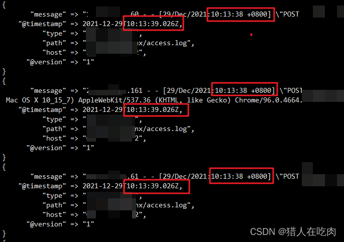
logstash 7. There is a time problem in X. the difference between @ timestamp and local time is 8 hours
Kettle paoding jieniu Chapter 17 text file output
Imx6 debugging LVDS screen technical notes
函数递归以及趣味问题的解决

Dynamically add default fusing rules to feign client based on sentinel + Nacos
QT tablewidget insert qcombobox drop-down box
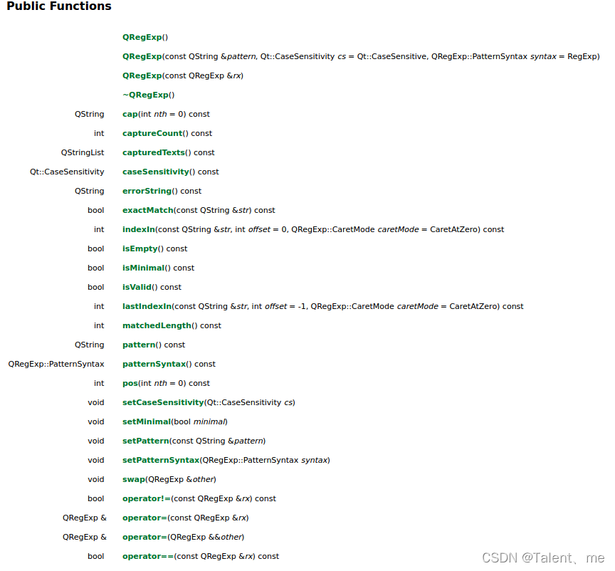
Use of regular expressions in QT
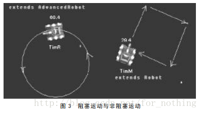
Robocode tutorial 8 - advanced robot

Docker 安装 MySQL

多功能工具箱微信小程序源码
随机推荐
【ACM】455. Distribute Biscuits (1. Give priority to big biscuits to big appetite; 2. Traverse two arrays with only one for loop (use subscript index -- to traverse another array))
How to install jsonpath package
Rust: how to match a string?
Mysqldump backup database
Test post and login function
Using transmittablethreadlocal to realize parameter cross thread transmission
解决报错max virtual memory areas vm.max_map_count [65530] is too low, increase to at least [262144]
QT curve / oscilloscope customplot control
Use of regular expressions in QT
CISSP certified daily knowledge points (April 19, 2022)
In win10 system, all programs run as administrator by default
PowerDesigner various font settings; Preview font setting; SQL font settings
Stm32mp157 wm8960 audio driver debugging notes
Spark performance optimization guide
C language to achieve 2048 small game direction merging logic
JD freefuck Jingdong HaoMao control panel background Command Execution Vulnerability
How to restore MySQL database after win10 system is reinstalled (mysql-8.0.26-winx64. Zip)
CISSP certified daily knowledge points (April 15, 2022)
Connection mode of QT signal and slot connect() and the return value of emit
Correct opening method of option