当前位置:网站首页>ADC
ADC
2022-04-22 06:06:00 【sameTimer】
1.Introduction
12 position ADC It is a successive approximation analog-to-digital converter (12 Bit resolution Collect voltage =Vref*ADC_DR/4096), As many as 18 Multiple channels allow measurement 16 Outside and 2 Internal signals . Different channels AD The transformation can be used as a single , continuity , scanning , Discontinuous patterns .ADC The result of the conversion can be left aligned or right aligned in 16 Bit data register . The analog watchdog can detect whether the input voltage is within the user-defined maximum and minimum voltage thresholds .ADC The clock is made of PCLK2 One generated by frequency division shall not exceed 14MHZ The clock signal of .
2.ADC main features
• 12-bit resolution
• Interrupt generation at End of Conversion, End of Injected conversion and Analog
watchdog event
• Single and continuous conversion modes
• Scan mode for automatic conversion of channel 0 to channel ‘n’
• Self-calibration
• Data alignment with in-built data coherency
• Channel by channel programmable sampling time
• External trigger option for both regular and injected conversion
• Discontinuous mode
• Dual mode (on devices with 2 ADCs or more)
• ADC conversion time:
– STM32F103xx performance line devices: 1 µs at 56 MHz (1.17 µs at 72 MHz)
– STM32F101xx access line devices: 1 µs at 28 MHz (1.55 µs at 36 MHz)
– STM32F102xx USB access line devices: 1.2 µs at 48 MHz
– STM32F105xx and STM32F107xx devices: 1 µs at 56 MHz (1.17 µs at 72 MHz)
• ADC supply requirement: 2.4 V to 3.6 V
• ADC input range: VREF- ≤ VIN ≤ VREF+
• DMA request generation during regular channel conversion
3.ADC functional description
1) ADC on-off control
By setting ADC_CR2 The register of ADON Flag bit to power on and start ,ADC The conversion takes place in ADON After one second . You can go through reset ADON Bit to abort the conversion and enter Power down Pattern , In this mode ADC There will be little loss of power .
2)ADC clock
The clock provided by the clock controller ADCCLK And PCLK2(APB2) Sync .RCC The controller has a function for ADC Programmable prescaler dedicated to clock .
3)Channel selection
16 A multiplexed channel . You can convert him into two groups : Rule group and injection group . A group consists of a series of transformations that can be completed in any order on any channel . such as , He can convert in the following sequence :Ch3,Ch5,Ch5...
Rule group : At most by 16 There are three transformations . The channel and number of conversions are determined by ADC_SQRx Registers and ADC_SQR1 Of L[3:0] Register specifies
Injection group : At most by 4 There are three transformations . The channel and number of conversions are determined by ADC_JSQR Registers and ADC_JSQR Of L[1:0] Register specifies
4) Single conversion mode
In single conversion mode ADC Make only one conversion . This mode can be determined by set ADC_CR2 In the register ADON Or external trigger bit , When CONT Bitwise 0 when :
Once a conversion is complete
Rule group :
The converted data is stored in 16 Bit ADC_DR In the register
EOC( Conversion end flag bit ) To be placed
If set EOCIE , An interrupt will generate
5) Continuous conversion mode
In continuous conversion mode ,ADC Start immediately after a conversion .set ADON Or triggered externally
CONT Position as 1:
6) Scanning mode :
This mode is used to scan a group of analog channels
adopt set ADC_CR1 The register of SCAN Bit to select the scanning mode , Once this mode is selected , adopt ADC_SQRx All channels selected by the register will be converted . A single transformation executes each of this group passageway . At the end of each conversion , The next channel of this group will automatically switch . If set CONT, The conversion will not end after the conversion of the last channel of the group is completed , Instead, continue the conversion from the first channel of the group .
But when using scan mode ,DMA The bit must be set , The direct memory access controller is used for each update ADC_DR regiseter Transfer the converted data of the rule group to SRAM. Each time the injection group is converted, the data is stored in ADC_JDRx In the register
7) Discontinuous mode
Rule group
Enable this mode by setting ADC_CR1 In register DISCEN. This mode can be converted through ADC_SQRx The of the sequence selected in the register is not greater than 8 Transformation sequence of . Through to the ADC_CR1 In register DISCNUM[2:0]bits Write a value to specify n.
When an external trigger occurs , Start switching to the next n individual ADC_SQRx The sequence selected in the register until all sequence conversions are completed . The total length of the sequence consists of ADC_SQR1 Of L[3:0] Appoint .
Example:
n = 3, channels to be converted = 0, 1, 2, 3, 6, 7, 9, 10
1st trigger: sequence converted 0, 1, 2. An EOC event is generated at each conversion
2nd trigger: sequence converted 3, 6, 7. An EOC event is generated at each
conversion
3rd trigger: sequence converted 9, 10. An EOC event is generated at each conversion
4th trigger: sequence converted 0, 1, 2. An EOC event is generated at each conversion
8) calibration
ADC There is a built-in calibration mode . Calibration is significantly reduced due to changes in the internal capacitor bank . During calibration , Will be for each one
Capacitor bank Calculate an error correction code , In all subsequent transformations , This code will be used to eliminate the error contribution of each capacitor bank .
By setting ADC_CR2 Of CAL Start calibration . Once the calibration is complete ,CAL Bits will be used by hardware reset And the normal conversion will be performed . It is recommended to start a correction when the power is on . The correction code will be stored in ADC_DR As long as the correction phase ends .
9) Data alignment
ADC_CR2 In register ALIGN bit Select the mode of data storage after conversion , Align left or right .
10) Programmable sampling time channel by channel
ADC The clock cycle for collecting the input voltage can be ADC_SMPR1 and ADC_SMPR2 In register SMP[2:0] change . Each channel can be sampled at different times .
The total sampling time can be calculated by the following formula :
Tconv = Sampling time + 12.5 cycles
For example, use ADCCLK=14MHZ, The sampling time is 1.5 A cycle
Tconv = 1.5 + 12.5 = 14 cycles = 1us
版权声明
本文为[sameTimer]所创,转载请带上原文链接,感谢
https://yzsam.com/2022/04/202204220542044850.html
边栏推荐
- Basic knowledge of software testing
- Intel SGX线程锁
- 11 - process control - for loop
- Chapter 86 leetcode refers to offer dynamic programming (III) maximum profit of stock
- 10 - process control - while loop statement
- Blue Bridge Cup 31 day sprint Day7
- stm32单片机与LD3320语音模块交互法一
- VB操作excel 格式设置及打印页面设置(精简)
- 正点原子stm32f429官方列程编译之后用J-LINK无法下载
- Characteristics and usage of QT signal and slot
猜你喜欢
QT添加pri编译运行: error: fatal error: no input files问题解决

12 - container - string

geojson文件shapefile文件 批量 互转 小工具
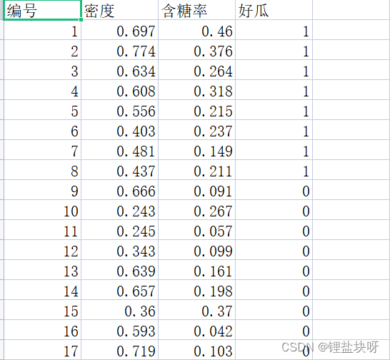
日常学习记录——读取自定义数据集

通用定时器

第72篇 LeetCode题目练习(五) 5.最长回文子串

Photoresist for learning of Blue Bridge Cup embedded expansion board
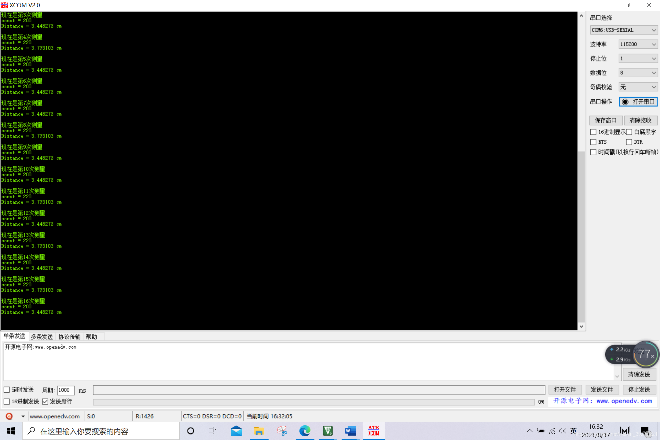
STM32 study notes 4 - HC_ Commissioning record of SR04 ultrasonic ranging module

Blue bridge sprint topic - BFS
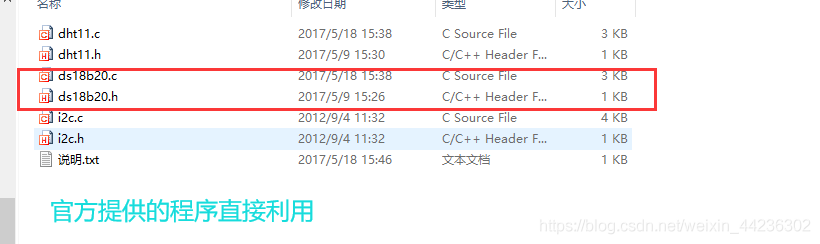
DS18B20 of Blue Bridge Cup embedded expansion board learning
随机推荐
STM32 learning note 3 - input pin of GPIO
RTL8367学习笔记3——ACL访问控制列表
Add a minimize button to the CPropertySheet window
Blue Bridge Cup 31 day sprint day16
Blue Bridge Cup embedded expansion board learning lis302dl
TXT文本内容逐个删除
11 - process control - for loop
Dlopen calls dynamic library
Why is softmax commonly used instead of sigmoid in binary classification tasks
hp unix上编译openssl并使用
Software test classification
The 7th Blue Bridge Cup embedded provincial competition: analog liquid level detection and alarm system "
日常学习记录——读取自定义数据集
jeecgboot-online在线开发3
Usage of tcpdump
Intel SGX线程锁
Oracle uses C language to write custom functions
Rtl8367 learning note 2 - network configuration operation literacy
用MOS管构成H桥的心得
dlopen调用动态库