1、UML The definition of
Unified modeling language (Unified Modeling Language,UML) It starts with 1997 One year OMG standard , It's for object-oriented Describe the products of the system 、 visualization and Organization A standard language for documentation , It's the third generation of generic modeling and specification languages .UML It's a modeling tool for object-oriented design , Independent of any specific programming language .
When it comes to software development , System designer / The system architect gives UML The design , Programmers will be based on UML Design drawings are coded / Development .
2、 Modeling tools
- IBM Rational Rose
- starUML
- MS Visio( The best thing is to draw a flow chart )
- .....
3、 common UML chart
- Class diagram (Class Diagram): Information describing a class , And the relationship information between classes .
- Use case diagram (Use Case Diagram): Standing in the system user ( System roles ) Of What are the functions of the angle analysis system .
- Sequence diagram (Sequence Diagram): Describe the execution of the program , method , The return value of the method .
4、 Class diagram (Class Diagram)
1) Definition of class diagram
Class diagram (Class Diagram): Information describing a class , And the relationship information between classes .
2) Draw a class diagram
- Usually in Rational Rose The tool Logical View Implementation class diagram under directory
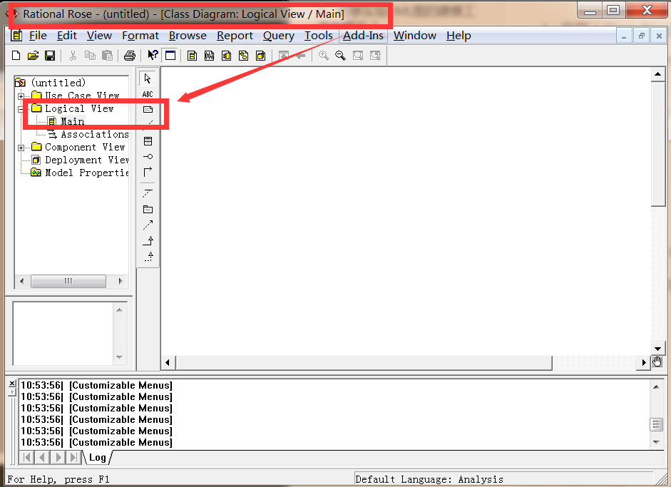
-
Structure directories are usually created

-
Create a class diagram
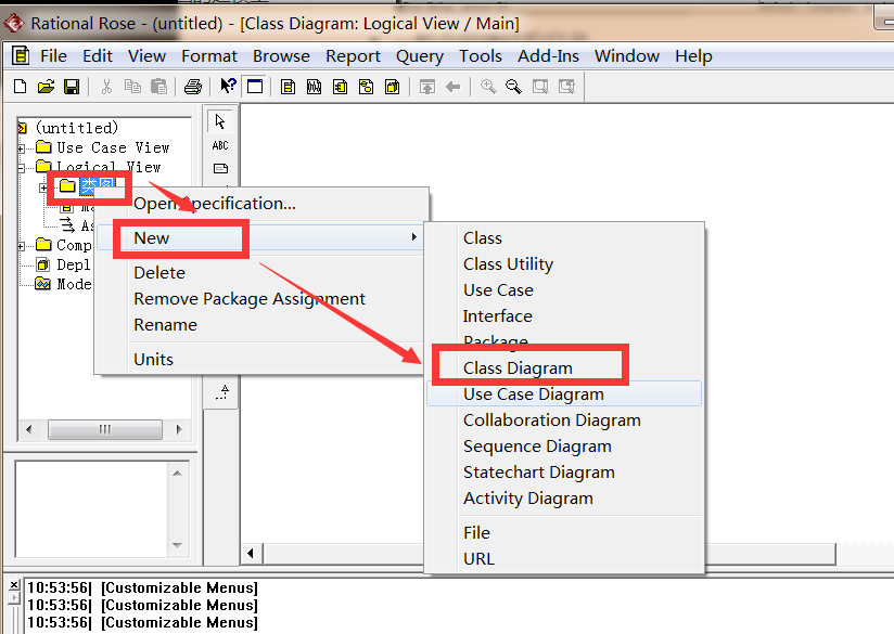

-
Write notes


-
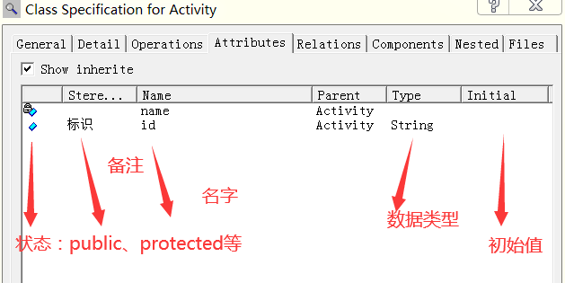
Create properties

-
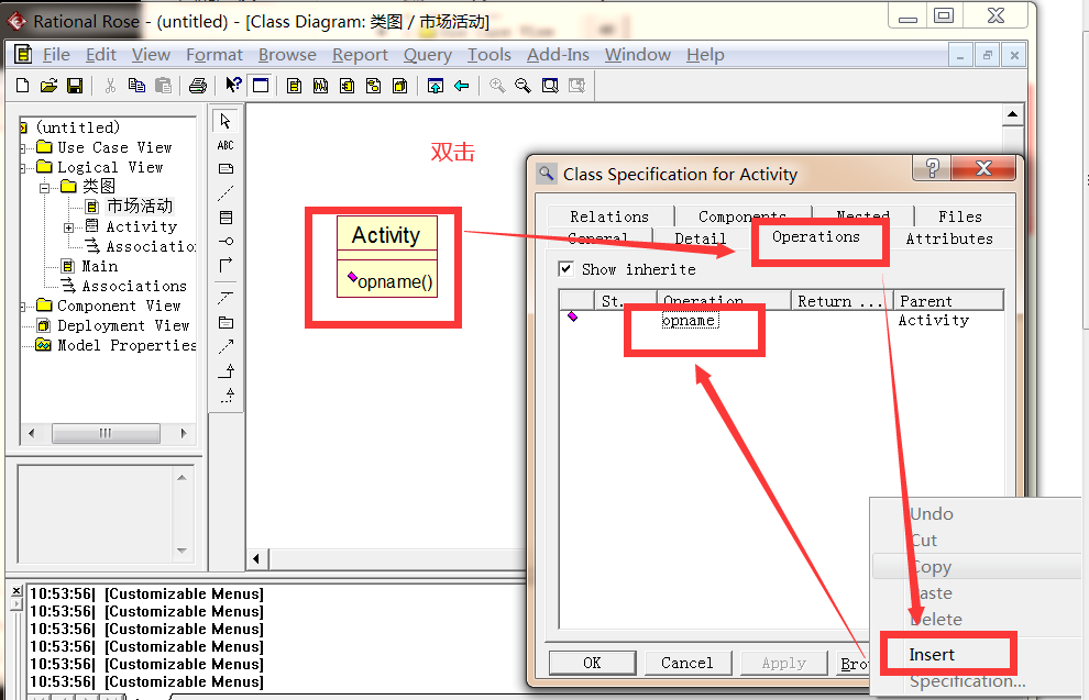
Create method ()
-
result

3) Six relationships
(1) Generalization relation (is a:Cat is a Animal--》 Inherit ): Classes and classes 、 Interfaces and interface inheritance .

(2) Realization relationship (like a:Cooker like a FoodMenu): Class implementation interface

(3) Connections (has a:Programmer has a Computer)


(4) Aggregate relationship
Aggregation relationship describes the relationship between whole and part , Aggregation is a special relationship . For example, there are multiple students in a classroom , The relationship between the classroom and students is the relationship between the whole and the part , In an aggregate relationship , The whole life cycle doesn't determine the part life cycle , for example : The classroom is gone , The students are still , Or the students are gone , The classroom is still there .

(5) synthetic relation
Combinatorial relationship can be regarded as a special aggregation relationship , The whole life cycle determines the part life cycle , The part is attached to the whole , It's impossible for a part to leave the whole “ Alive ”. For example, the relationship between people and limbs .

(6) Dependency relationship
Dependency is the weakest of all relationships , This relationship is generally reflected between classes and local variables .

5、 Use case diagram (Use Case Diagram)
1) Definition of use case diagram
Standing in the system user ( System roles ) What are the functions of the system .
When implementing use case diagrams , We need to extract system roles first .
2) Implementation use case diagram

6、 Sequence diagram (sequence diagram)
1) Definition of sequence diagram
The method calling process is described in the sequence diagram , Procedure execution flow , And the return value at the end of method execution .
2) Implementation sequence diagram
The sequence diagram is usually in Rational Rose Of Logical view To realize
An example in the use case diagram corresponds to a sequence diagram in the sequence diagram . How does the timing diagram describe a function , What is the process .

3) notes
- Villain : The initiator of the action
- rectangular / Small circle : object
- Implement arrow : call
- Dashed arrow : return
- Columnar : Object lifecycle , The column cannot be broken , It can't be broken in the same process .
- Fold back line : The current class is invoked by other methods in its middle note. .