目录
- STC8H开发(一): 在Keil5中配置和使用FwLib_STC8封装库(图文详解)
- STC8H开发(二): 在Linux VSCode中配置和使用FwLib_STC8封装库(图文详解)
- STC8H开发(三): 基于FwLib_STC8的模数转换ADC介绍和演示用例说明
- STC8H开发(四): FwLib_STC8 封装库的介绍和使用注意事项
- STC8H开发(五): SPI驱动nRF24L01无线模块
- STC8H开发(六): SPI驱动ADXL345三轴加速度检测模块
- STC8H开发(七): I2C驱动MPU6050三轴加速度+三轴角速度检测模块
- STC8H开发(八): NRF24L01无线传输音频(对讲机原型)
- STC8H开发(九): STC8H8K64U模拟USB HID外设
- STC8H开发(十): SPI驱动Nokia5110 LCD(PCD8544)
- STC8H开发(十一): GPIO单线驱动多个DS18B20数字温度计
- STC8H开发(十二): I2C驱动AT24C08,AT24C32系列EEPROM存储
- STC8H开发(十三): I2C驱动DS3231高精度实时时钟芯片
- STC8H开发(十四): I2C驱动RX8025T高精度实时时钟芯片
- STC8H开发(十五): GPIO驱动Ci24R1无线模块
Ci24R1 简介

Ci24R1是Si24R1的SOP8A simplified version of the package, The manufacturer is Nanjing Zhongkewei, They also have a more common model isSi24R1, Si24R1It is very widely usednRF24L1的克隆版. Ci24R1communication protocol andSi24R1, nRF24L01是兼容的, Also supports BluetoothBLE4.2标准.
具体到参数上, 与nRF24L01类似, 都是2.4GHzfrequency band wireless communication chip, 官网的介绍: 低成本高性能2.4GHz 无线收发芯片(Bluetooth version is supported). 专为低功耗无线场合设计,集成嵌入式ARQ基带协议引擎的无线收发器芯片. 工作频率范围为2400MHz-2525MHz,共有126个1MHz带宽的信道, 支持2Mbps,1Mbps,250Kbps三种数据速率, 支持发射BLE4.2标准的数据包,可以方便的向手机传输数据.
主要特性
- 频段: 2.4GHz ISM
- 调制方式: GFSK/FSK
- 数据速率: 2Mbps/1Mbps/250Kbps
- 关断功耗: 1uA
- 待机功耗: 15uA
- 快速启动时间: ≤ 130uS
- 内部集成高PSRR LDO
- 宽电源电压范围: 1.9-3.6V
- 宽数字I/O电压范围:1.9-5.25V
- 低成本晶振: 16MHz±60ppm
- 接收灵敏度: -83dBm @2MHz
- 最高发射功率: 7dBm
- 接收电流(2Mbps): 15mA
- 发射电流(2Mbps): 12mA(0dBm)
- 支持三线SPI接口
- 内部集成智能ARQ基带协议引擎
- 收发数据硬件中断输出
- 支持1bit RSSI 输出
- 极少外围器件,降低系统应用成本
- 封装: SOP8, DFN8(220.8mm)
target chip
Ci24R1对标的是2.4G SOP8芯片, Mainly for cheap products with wireless communication needs, There are mainly such chips XN297, XN297L, XL2400/WL2400, all three linesSPI通信, All you need is a crystal and a capacitor or two, There are very few peripheral circuits. Ci24R1The advantage is that both are supported 2.4GHz 和 BLE4.2.
The pin layouts of these types of chips are different, And the way of driving is not the same.
Ci24R1 管脚和典型电路
管脚布局
SOP8封装(左) 和 DFN8封装(右)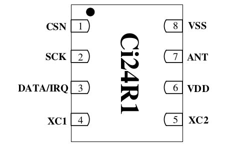

管脚定义
| PIN | Name | I/O | 说明 |
|---|---|---|---|
| 1 | CSN | DI | SPI 片选信号 |
| 2 | SCK | DI | SPI 时钟信号 |
| 3 | DATA/IRQ | IO | SPI 数据输入/输出/中断信号 |
| 4 | XC1 | AI | 晶振输入 |
| 5 | XC2 | AO | 晶振输出 |
| 6 | VDD | Power | 电源(+2.1 ~ +3.6V,DC) |
| 7 | ANT | RF | 天线接口 |
| 8 | VSS | GND | 地 |
电路

STC8H 驱动 Ci24R1
驱动说明
Test code provided by the manufacturer, 都是基于GPIO模拟SPI驱动, At first I thought I could use hardwareSPI驱动, 后来在STC8H上测试, 发现不可行, 主要存在两个问题
- Ci24R1仅仅提供了一个DATA口, 对应SPI的MOSI, But still reusedIRQ, 所以使用硬件SPI的话, 需要随时切换MOSI pin的工作状态
- STC8H的硬件SPI驱动时, There is a 50% chance of not being able to read correctly, 得到的全是0xFF
- STC8H即使用GPIO模拟驱动SPI, 也必须将IOmode is set to push-pull, Reading and writing is normal when using quasi-bidirectional, But sending fails, 尚不清楚原因
接线
示例代码中, Used with hardwareSPI一样的Pin, Actually replace it with something elsePin也一样, 因为都是通过GPIO模拟驱动.
P35(SS, Ignored) => CSN
P34(MOSI)        => DATA
P32(SPCLK)       => SCK
                    VDD1     => 3.3V
                    XC1,XC2  => 16MHz OSC
                    GND      => GND
示例代码
代码下载地址
- GitHub https://github.com/IOsetting/FwLib_STC8/tree/master/demo/gpio/ci24r1
- Gitee https://gitee.com/iosetting/fw-lib_-stc8/tree/master/demo/gpio/ci24r1
基础宏定义
Switch the transceiver mode, 通过main.c中的
// 0:TX, 1:RX
#define CI24R1_MODE 1
因为涉及到对MOSI Pin的模式切换, 涉及到对CElevel operation(寄存器写), This part uses macro definitions to ensure performance
#define CI24R1_CSN  P35
#define CI24R1_MOSI P34
#define CI24R1_SCK  P32

#define CI24R1_DATA_OUT()        GPIO_P3_SetMode(GPIO_Pin_4, GPIO_Mode_Output_PP)
#define CI24R1_DATA_IN()         GPIO_P3_SetMode(GPIO_Pin_4, GPIO_Mode_Input_HIP)
#define CI24R1_DATA_LOW()        CI24R1_MOSI = 0
#define CI24R1_DATA_HIGH()       CI24R1_MOSI = 1
#define CI24R1_DATA_READ()       CI24R1_MOSI

#define CI24R1_CLK_LOW()         CI24R1_SCK = 0
#define CI24R1_CLK_HIGH()        CI24R1_SCK = 1

#define CI24R1_NSS_LOW()         CI24R1_CSN = 0
#define CI24R1_NSS_HIGH()        CI24R1_CSN = 1

#define CI24R1_CE_LOW()          CI24R1_WriteReg(CI24R1_CMD_CE_OFF, CI24R1_CMD_NOP)
#define CI24R1_CE_HIGH()         CI24R1_WriteReg(CI24R1_CMD_CE_ON, CI24R1_CMD_NOP)
模拟SPI基础通信
void CI24R1_WriteByte(uint8_t value)
{
    uint8_t i = 0;
    CI24R1_CLK_LOW();
    CI24R1_DATA_OUT();
    for (i = 0; i < 8; i++)
    {
        CI24R1_CLK_LOW();
        if (value & 0x80)
        {
            CI24R1_DATA_HIGH();
        }
        else
        {
            CI24R1_DATA_LOW();
        }
        CI24R1_CLK_HIGH();
        value = value << 1;
    }
    CI24R1_CLK_LOW();
}

uint8_t CI24R1_ReadByte(void)
{
    uint8_t i = 0, RxData;

    CI24R1_DATA_IN();
    CI24R1_CLK_LOW();
    for (i = 0; i < 8; i++)
    {
        RxData = RxData << 1;
        CI24R1_CLK_HIGH();
        if (CI24R1_DATA_READ())
        {
            RxData |= 0x01;
        }
        else
        {
            RxData &= 0xfe;
        }
        CI24R1_CLK_LOW();
    }
    CI24R1_CLK_LOW();
    return RxData;
}
Ci24R1 single-byte command, 寄存器读写
对nRF24L01Familiar with the way its registers are read and written, In fact, it is a two-byte communication, Ci24R1The special place is that there is a single-byte write command, 用于切换DATA Pin的模式
void CI24R1_WriteReg(uint8_t reg,uint8_t value)
{
    CI24R1_NSS_LOW();
    CI24R1_WriteByte(reg);
    CI24R1_WriteByte(value);
    CI24R1_NSS_HIGH();
}

uint8_t CI24R1_ReadReg(uint8_t reg)
{
    uint8_t reg_val;
    CI24R1_NSS_LOW();
    CI24R1_WriteByte(reg);
    reg_val = CI24R1_ReadByte();
    CI24R1_NSS_HIGH();
    return reg_val;
}

void CI24R1_WriteCmd(uint8_t cmd)
{
    CI24R1_NSS_LOW();
    CI24R1_WriteByte(cmd);
    CI24R1_NSS_HIGH();
}
Ci24R1 multibyte read and write commands
void CI24R1_WriteFromBuf(uint8_t reg, const uint8_t *pBuf, uint8_t len)
{
    uint8_t ctr;
    CI24R1_NSS_LOW();
    CI24R1_WriteByte(reg);
    for (ctr = 0; ctr < len; ctr++)
    {
        CI24R1_WriteByte(*pBuf++);
    }
    CI24R1_NSS_HIGH();
}

void CI24R1_ReadToBuf(uint8_t reg, uint8_t *pBuf, uint8_t len)
{
    uint8_t ctr;
    CI24R1_NSS_LOW();
    CI24R1_WriteByte(reg);
    for (ctr = 0; ctr < len; ctr++)
    {
        pBuf[ctr] = CI24R1_ReadByte();
    }
    CI24R1_NSS_HIGH();

}
Ci24R1 的初始化
There are a few things to note about initialization
- CONFIG的最后一个bit标识是TX还是RX
- The address width is used without special cases5 bytes
- payloadwhether to widen, 如果是, then you don't need to define eachpipe的payload宽度, 如果否, A correspondence must be definedpipe的payload宽度(CI24R1_REG_RX_PW_Px), Otherwise there will be no reception
- Whether it is wider will also affect CI24R1_REG_FEATURE 中的一位
- 如果开启ACK, TX地址和RX P0The address must be the same, Communication between the two modules can be used exactly the sameTX和RX P0
开始测试时, Low bitrates can be used(250Kbps)Increase power(11dB), In addition, the modules can be closer together, For example, five or six centimeters, Avoid non-programmatic problems that cause debugging to fail
void CI24R1_Init(void)
{
    CI24R1_CE_LOW();
#if (CI24R1_PLOAD_WIDTH == 0)
    // Enable dynamic payload length on pipe 0 and pipe 1
    CI24R1_WriteReg(CI24R1_CMD_W_REGISTER | CI24R1_REG_DYNPD, 0x03);
    CI24R1_WriteReg(CI24R1_CMD_W_REGISTER | CI24R1_REG_FEATURE, 0x07);
#else
    // Fixed payload length
    CI24R1_WriteReg(CI24R1_CMD_W_REGISTER | CI24R1_REG_DYNPD, 0x00);
    CI24R1_WriteReg(CI24R1_CMD_W_REGISTER | CI24R1_REG_FEATURE, 0x03);
    // Length of pipe 0
    CI24R1_WriteReg(CI24R1_CMD_W_REGISTER | CI24R1_REG_RX_PW_P0, CI24R1_PLOAD_WIDTH);
    // Length of pipe 1
    CI24R1_WriteReg(CI24R1_CMD_W_REGISTER | CI24R1_REG_RX_PW_P1, CI24R1_PLOAD_WIDTH);
#endif
    CI24R1_WriteReg(CI24R1_CMD_W_REGISTER | CI24R1_REG_CONFIG, 0x0E);
    // Enable auto ack all pipes
    CI24R1_WriteReg(CI24R1_CMD_W_REGISTER | CI24R1_REG_EN_AA, 0x3F);
    // Enable all pipes
    CI24R1_WriteReg(CI24R1_CMD_W_REGISTER | CI24R1_REG_EN_RXADDR, 0x3F);
    // Address width, 0x1:3bytes, 0x02:4bytes, 0x3:5bytes
    CI24R1_WriteReg(CI24R1_CMD_W_REGISTER | CI24R1_REG_SETUP_AW, 0x03);
    // Resend 500us and 3 times. interval: 250us * ([0, 15] + 1), retries: [0, 15]
    CI24R1_WriteReg(CI24R1_CMD_W_REGISTER | CI24R1_REG_SETUP_RETR, (0x01 << 4) | 0x03);
    // RF Data Rate 250K 11db
    CI24R1_WriteReg(CI24R1_CMD_W_REGISTER | CI24R1_REG_RF_SETUP, CI24R1_RF_SETUP_1M | CI24R1_RF_SETUP_11DB);
    CI24R1_CE_HIGH();
}
Ci24R1 发送
The sending follows the example given by the manufacturer, Sending content in writing, 拉高CE后, 立即切换IOAn interrupt that goes to the input state and waits for the result to be sent. 如果是MAX_RT中断, 说明发送失败, 需要清空TX_FIFO和标志位.
void CI24R1_SetTxMode(void)
{
    uint8_t value;
    value = CI24R1_ReadReg(CI24R1_CMD_R_REGISTER | CI24R1_REG_CONFIG);
    value &= 0xFE;
    CI24R1_WriteReg(CI24R1_CMD_W_REGISTER | CI24R1_REG_CONFIG, value);
}

uint8_t CI24R1_Tx(uint8_t *ucPayload, uint8_t length)
{
    uint8_t status;
#if (CI24R1_PLOAD_WIDTH == 0)
    CI24R1_WriteFromBuf(CI24R1_CMD_W_TX_PAYLOAD, ucPayload, length);
#else
    CI24R1_WriteFromBuf(CI24R1_CMD_W_TX_PAYLOAD, ucPayload, CI24R1_PLOAD_WIDTH);
#endif
    CI24R1_CE_HIGH();
    CI24R1_WriteCmd(CI24R1_CMD_SELIRQ);
    CI24R1_DATA_IN();
    while (CI24R1_DATA_READ());
    CI24R1_DATA_OUT();
    CI24R1_WriteCmd(CI24R1_CMD_SELSPI);
    status = CI24R1_ReadStatus();
    if (status & CI24R1_FLAG_MAX_RT)
    {
        CI24R1_WriteReg(CI24R1_CMD_FLUSH_TX, CI24R1_CMD_NOP);
    }
    // Clear status flags
    CI24R1_WriteReg(CI24R1_CMD_W_REGISTER | CI24R1_REG_STATUS, status);
    return status;
}
Ci24R1 接收
The example of the manufacturer is also used, After switching to the input state, Blocks waiting to receive an interrupt. If testing, SPIReading and writing is no problem, The distance is also close enough, But it never stopped, 可以检查一下
两个模块的TX地址和RX_P0地址, RF Channel是否一致, Whether the correspondence is enabledRX Pipe, 如果是固定宽度, Whether it is in the corresponding receptionpipeis set correctly.
void CI24R1_SetRxMode(void)
{
    uint8_t value;
    value = CI24R1_ReadReg(CI24R1_CMD_R_REGISTER | CI24R1_REG_CONFIG);
    value |= 0x01;
    CI24R1_WriteReg(CI24R1_CMD_W_REGISTER | CI24R1_REG_CONFIG, value);
}

uint8_t CI24R1_Rx(void)
{
    uint8_t i, status, rxplWidth;
    CI24R1_WriteReg(CI24R1_CMD_FLUSH_RX, CI24R1_CMD_NOP);
    CI24R1_WriteReg(CI24R1_CMD_SELIRQ, CI24R1_CMD_NOP);
    CI24R1_DATA_IN();
    while(CI24R1_DATA_READ());
    CI24R1_DATA_OUT();
    CI24R1_WriteReg(CI24R1_CMD_SELSPI, CI24R1_CMD_NOP);
    status = CI24R1_ReadStatus();
    UART1_TxChar('>');
    UART1_TxHex(status);
    if (status & CI24R1_FLAG_RX_READY)
    {
#if CI24R1_PLOAD_WIDTH == 0
        rxplWidth = CI24R1_ReadReg(CI24R1_CMD_R_RX_PL_WID);
#else
        rxplWidth = CI24R1_PLOAD_WIDTH;
#endif
        // Read RX to buffer
        CI24R1_ReadToBuf(CI24R1_CMD_R_RX_PAYLOAD, xbuf, rxplWidth);
        // Clear status flags
        CI24R1_WriteReg(CI24R1_CMD_W_REGISTER | CI24R1_REG_STATUS, status);
        UART1_TxChar('>');
        for (i = 0; i < rxplWidth; i++)
        {
            UART1_TxHex(*(xbuf_data + i));
        }
    }
    return status;
}
结束
测试中Ci24R1communication is relatively stable, 因为IOConversion plus simulationSPI, communication rate and4线SPI的nRF24L01和Si24R1There will definitely be a difference, The advantage is that you save oneIO.
This chip market direction is very obvious, It is for cost- and size-sensitive markets, 仅需要GPIO就能使用, 几乎所有的MCU都能兼容. Remote control for cheap toys and home appliances, These products are used in large quantities8pin的8位MCU, 这种MCU总共只有6个可用IO, 省一个IOA lot of possibilities can be increased. There are other integrations of the same type on the marketMCU的型号, 例如XL2401, XL2402, SOP16Encapsulated with wireless tapeMCU不到1.4CNY, Costs can be kept very low, It is also beneficial to production and quality control after integration.