当前位置:网站首页>Calibration principle of robot tool coordinate system
Calibration principle of robot tool coordinate system
2022-04-22 06:09:00 【From deliberate to habit】
Tool coordinate system
The default tool coordinate system is based on the flange center point ,XYZ A coordinate system with a fixed direction . Any other tool installed on the end flange ,TCP The position of the point is fixed relative to the center point of the flange , With this TCP Establishing a tool coordinate system for the origin can actually be seen as translation and rotation relative to the end .
calibration
During the use of industrial robots, different tools are often installed on the flange surface of the end of the robot to meet the actual production needs , In order to accurately control the position and attitude of tool movement , It is necessary to calibrate the coordinate system of the tool . The cooperative arm robot I use provides three methods : Direct input method 、 Four point method and six point method . The four point method is suitable for changing only the origin of the tool coordinate system TCP The location of , Only when the default tool coordinate system is translated . That is, when the new tool is only... Relative to the default coordinate system TCP Location ( namely X、Y、Z) Change , And posture ( namely W、P、R) It hasn't changed , The tool coordinate system can be established by four point calibration method in practical use , The six point method is applicable to the origin of the tool coordinate system (TCP) Your position and posture have changed , When not only the default tool coordinate system is translated but also rotated . When TCP And posture change , Then we need to use the six point method to establish a new tool coordinate system .
Let's focus on “ The six point method ”
1. Calibration procedure
(1) Find a very accurate fixed point within the action range of the robot as the reference point ;
(2) Determine a reference point on the tool ( It's better to be the center point of the tool Tool Center Point, TCP);
(3) Manual manipulation of robots TCP, With four different tool postures, it just meets the fixed point .
Any attitude of the first three points , The fourth point is that the reference point of the tool is perpendicular to the fixed point , The fifth point is the tool reference point from the fixed point to the point to be set TCP Of x direction , The sixth point is the tool reference point from the fixed point to the point to be set TCP The in z direction ,( When taking points, there are x,y Point selection method of direction , Also have x,z Point selection method of direction , It depends on the robot ), As shown in the figure below :

2. Calibration process
TCP Calibration process


Personally, I think the number in the matrix depends on RPY(z,y,x), Or Euler angle (z,y,z), Two different approaches , The formula is different , The calculation method can be referred to Introduction to Robotics – Analysis control and application


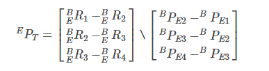
because EPT by 3x1 Column vector , And the right side of the equation is 9x3 Matrix , Therefore, the equations are incompatible equations , It is not allowed to directly use the method of solving non-homogeneous linear equations or solve solve . The matrix form of least square method is adopted , One problem with using least squares is that the resulting number is an estimate , There will be some error . Because its coefficient matrix is not a square matrix , No direct inversion , Therefore, the generalized inverse is used . You can use it directly MATLAB The corresponding function is solved , Convenient and quick .
Tool coordinate system attitude (TCF) calibration
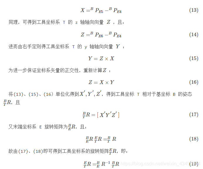
In the 1 Part of the tool coordinate system has been obtained (TCF) The location of , And calculation TCP The posture adopts z/x Direction calibration .
The process, TCF Your posture remains the same ( As in the first section – The basic steps are shown in the figure ). Take the first attitude calibration point as the position point 4( The following figure is marked as the calibration point 1); The robot moves from the position point 4 set out , Along the +x Move a certain distance in the direction to get the position point 5( The following figure is marked as the calibration point 2); The robot moves from the position point 4 set out , Along the +z Move a certain distance in the direction to get the position point 6( The following figure is marked as the calibration point 3). As shown in the figure below :

because 3 One of the calibration points TCF The posture remains the same , so BERi=4,5,6 All equal , And by the (12) have to EPT remain unchanged , Therefore, the tool coordinate system can be obtained T Of x Axial vector X , And :
obviously ,TCF The minimum condition of six point calibration is that 6 The position and pose of two position points
And to enable the formula to solve , The location point shall be ensured 1,2,3,4 Not on the same plane .
test result
The deviation of translation parameters calculated by the above method is large , The calculation error of multiple groups of data is within ±7cm about ,
So you need to check carefully when using , The angle offset method calculates many groups , forbid . The summary mainly explains the calibration method and general calculation process of tool coordinate system , In actual calibration , Robot comes with calibration calculation , The data can be recorded according to the above six point method , Complete the calibration on the operation box

This data is the final result of calibrating the oil gun at the end of the robot TCP/TCF Parameters , Get the data and adjust it to the tool coordinate system , The parameter sign can be verified by actual operation
principle
For industrial robots , Base coordinates B And Coordinate system of the end flange face T The relationship between them has been set up when making robots , Every time the manipulator is moving , The rotation angle of each joint is changing , Then calculate the coordinate system transformation of each joint , The specific principle can refer to the robot D-H Construction of coordinate system . This paper simplifies the relationship , Assume the base coordinates B Coordinate system with the end flange face E The transformation matrix between is ![[ The formula ]](/img/20/1be15b733c73a11aa9e717c78811fe.png)
. The transformation matrix between the tool coordinate system and the end coordinate system is ![[ The formula ]](/img/87/681669dfdafea6c159f2deba2ecd97.png)
, The three coordinate systems have the following relationship :


Because the position relationship between the tool and the end flange surface of the robot is fixed , The calibration process is to calibrate the coordinate system of the robot tool T And robot end coordinate system E The relationship between , It means the position relationship between the tool coordinate system and the robot end coordinate system , The calibration type is similar to hand eye calibration . The calibration process can be divided into two parts , Position of tool center point (TCP) calibration , Tool coordinate system attitude calibration (TCF) .
reference :
Kang Cunfeng , Wang Hongwei , Zhang Pengfei et al . Research and implementation of tool coordinate system calibration of welding robot [j]. Journal of Beijing University of Technology 2016, 42(1).
版权声明
本文为[From deliberate to habit]所创,转载请带上原文链接,感谢
https://yzsam.com/2022/04/202204220542471425.html
边栏推荐
猜你喜欢
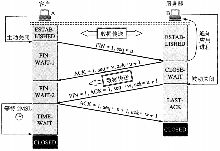
常见面试问题 - 2(计算机网络)
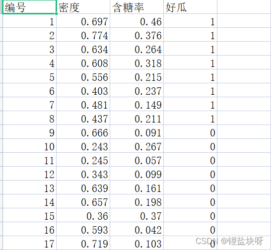
Daily learning records - reading custom data sets

Chorme debugging tool

QT中出现error: undefined reference to `Widget::SetTime()‘
DS18B20 of Blue Bridge Cup embedded expansion board learning

蓝桥杯嵌入式扩展板学习之光敏电阻

Chapter 89 leetcode refers to offer dynamic programming (6) translating numbers into strings

Characteristics and usage of QT signal and slot

记录AD软件学习之坑

正点原子stm32f429官方列程编译之后用J-LINK无法下载
随机推荐
Daily learning records - reading custom data sets
Blue Bridge Cup embedded expansion board learning DHT11
Pytorch deep learning practice_ 10 basis of convolutional neural network CNN
Why is softmax commonly used instead of sigmoid in binary classification tasks
Jeecgboot Online form Development - control Configuration
Code color difference of QT learning
ADC key for learning of Blue Bridge Cup embedded expansion board
Setting time and date display of QT learning
Record the pit of ad software learning
TCP通讯MODBUS协议解析
STM32 printf redirection virtual oscilloscope
PyGame simple aircraft war
chorme调试工具
机器人工具坐标系标定原理
Assemble DOS interrupt function
剑指 Offer II 022. 链表中环的入口节点
Interaction method II between STM32 single chip microcomputer and ld3320 voice module
Compiling OpenSSL of arm64 on M1 chip
c#委托、线程、定时器学习感悟
Part 72 leetcode exercise (V) 5 Longest Palindromic Substring