当前位置:网站首页>Physical meaning of FFT: 1024 point FFT is 1024 real numbers. The actual input to FFT is 1024 complex numbers (imaginary part is 0), and the output is also 1024 complex numbers. The effective data is
Physical meaning of FFT: 1024 point FFT is 1024 real numbers. The actual input to FFT is 1024 complex numbers (imaginary part is 0), and the output is also 1024 complex numbers. The effective data is
2022-04-23 19:29:00 【ToneChip】
2019.02.19 Update for convenience and simplicity, remember FFT, Sum up two paragraphs to record
1024 spot FFT Medium 1024 It refers to the number of input real numbers , however FFT The input is usually a complex number , That is to say 1024 Plural .FFT The output is 1024 Plural , Only before calculation 512 Plural
summary
N spot FFT Medium N It refers to the number of input real numbers , however FFT The input of a function is usually a complex number , That is to say N Plural .FFT The output is N Plural , Only before calculation N/2 Plural
① FFT The physical meaning of the results
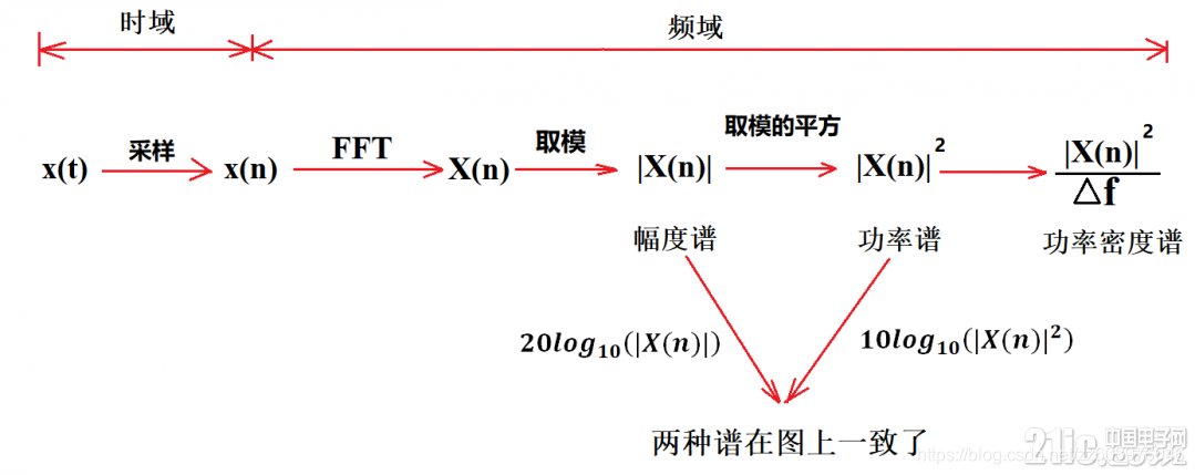
FFT Physical meaning
FFT It's a fast algorithm for DFT , A signal can be transformed
To the frequency domain . So as to analyze the frequency domain characteristics of the signal . Commonly used in spectrum analysis .
The time domain signal passes directly through ADC Sample to obtain .
Sampling points
- The sampling frequency is more than twice the signal frequency
- N A sampling point , after FFT after , You can get N Point FFT result . For convenience FFT operation , Usually N take 2 Integer power of .
The significance of the results
- The number of sampling points is N. that FFT And the result is a N Some of the plural . Every point corresponds to a frequency point .
- Suppose the peak value of the original signal is A, that FFT Every point of the result ( Except for the DC component of the first point ) The modulus of is A Of N/2 times . And the first point is the DC component , Its modulus is the DC component N times .
- Frequency points correspond to FFT As a result, the phase of the signal under the included angle of the complex number .
- The first point represents the DC component ( namely 0Hz), And the last point N The next point of ( Actually this point doesn't exist , Here is the hypothetical number N + 1 A little bit , It can also be seen as dividing the first point into two halves , The other half moves to the end ) It means the sampling frequency Fs, In the middle was N - 1 Divide the points equally N Equal parts , The frequency of each point increases in turn . For example, at some point n The frequency is :
Fn = (n - 1) * Fs / N.Fn It can be distinguished that the frequency is Fs/N, If the sampling frequency Fs by 1024Hz, The number of sampling points is 1024 spot , You can tell 1Hz, Each point is 1Hz. be aware 0Hz Is the first point, not the coordinate origin If you want to improve the frequency resolution , The number of sampling points must be increased , That is, the sampling time . Frequency resolution and sampling time are reciprocal . To improve the frequency resolution , You need to increase the number of sampling points , This is unrealistic in some practical applications , The analysis needs to be completed in a short time . The way to solve this problem is frequency subdivision , The simpler way is to sample the signal with shorter time , Then add a certain amount of 0, Make its length reach the required number of points , Do it again FFT, This can improve the frequency resolution to a certain extent . The specific frequency subdivision method can refer to the relevant literature .
summary
hypothesis FFT And then something n In the plural a+bi Express , So the module of the complex number is An= Radical sign a*a+b*b, Phase is Pn=atan2(b,a), Range from -pi To pi. Based on the above results , You can figure it out n The expression of the signal corresponding to the point is :
n = 1
    A1 / N

n ≠ 1, And n <= N / 2
    An / (N / 2) * cos(2 * pi * Fn * t + Pn)
 namely
    2 * An / N * cos(2 * pi * Fn * t + Pn).
example
expression
S = 2                                           // ①
  + 3.0 * cos(2 * pi * 50 * t - pi * 30 / 180)  // ②
  + 1.5 * cos(2 * pi * 75 * t + pi * 90 / 180)  // ③
The signal ① 2V The DC component of
The signal ② frequency 50Hz、 phase -30 degree 、 Range 3.0V The AC signal of
The signal ③ frequency 75Hz、 phase +90 degree 、 Range 1.5V The AC signal of
sampling
sampling frequency 256Hz
Number of sampling points 256 spot
according to Fn = (n - 1) * Fs / N, The first n The frequency of a point is n - 1. It can be known that the three signals are on the 1 A little bit 、 The first 51 A little bit 、 The first 76 There are peaks at points . Other points should be close to 0.
FFT Calculation
1 spot : 512         + 0i
2 spot : -2.6195E-14 - 1.4162E-13i
3 spot : -2.8586E-14 - 1.1898E-13i

50 spot :-6.2076E-13 - 2.1713E-12i
51 spot :332.55      - 192i
52 spot :-1.6707E-12 - 1.5241E-12i

75 spot :-2.2199E-13 - 1.0076E-12i
76 spot :3.4315E-12  + 192i
77 spot :-3.0263E-14 + 7.5609E-13i
Calculate the amplitude
according to An= Radical sign a*a+b*b Calculate the modulus
 1 spot : 512 =  Radical sign (512 * 512 + 0 * 0)
51 spot : 384 =  Radical sign (332.55 * 332.55 + 192 * 192)
76 spot : 192 =  Radical sign ((3.4315E-12) * 3.4315E-12) + 192 * 192)
according to
n = 1
    A1 / N

n ≠ 1, And n <= N / 2
    An / (N / 2) * cos(2 * pi * Fn * t + Pn)
 namely
    2 * An / N * cos(2 * pi * Fn * t + Pn).
You can calculate the amplitude
 1 spot : 2.0 = A1 / N       = 512 / 256
51 spot : 3.0 = An / (N / 2) = 384 / ( 256 / 2)
76 spot : 1.5 = An / (N / 2) = 192 / ( 256 / 2)
Calculate the phase
according to Pn=atan2(b,a) Calculate radian phase
 1 spot :  The DC component has no phase
51 spot : atan2(-192, 332.55)    = -0.5236
76 spot : atan2(192, 3.4315E-12) = 1.5708
Convert to angle
51 spot : 180 * (-0.5236) / pi = -30.0001
76 spot : 180 * (1.57080) / pi = +90.0002
Reference article Matlab routine
close all;        % Close all pictures first
Adc=2;            % DC component amplitude
A1=3;             % frequency F1 Signal amplitude
A2=1.5;           % frequency F2 Signal amplitude
F1=50;            % The signal 1 frequency (Hz)
F2=75;            % The signal 2 frequency (Hz)
Fs=256;           % sampling frequency (Hz)
P1=-30;           % The signal 1 phase ( degree )
P2=90;            % Signal phase ( degree )
N=256;            % Number of sampling points
t=[0:1/Fs:N/Fs];  % Sampling time

% The signal
S=Adc+A1*cos(2*pi*F1*t+pi*P1/180)+A2*cos(2*pi*F2*t+pi*P2/180);

% Display the original signal
plot(S);
title('signal');

figure;
Y = fft(S,N);                 % do FFT Transformation
Ayy = (abs(Y));               % modulus
plot(Ayy(1:N));               % Show original FFT Modulus results
title('Frequency spectrum');

figure;
Ayy=Ayy/(N/2);                % Convert to actual amplitude
Ayy(1)=Ayy(1)/2;
F=([1:N]-1)*Fs/N;             % Convert to actual frequency value
plot(F(1:N/2),Ayy(1:N/2));    % Displays the converted FFT Modulus results
title('Amplitude-frequency');

figure;
Pyy=[1:N/2];
for i=1:N/2
 Pyy(i)=phase(Y(i));          % Calculate the phase
 Pyy(i)=Pyy(i)*180/pi;        % Convert to angle
end;
plot(F(1:N/2),Pyy(1:N/2));    % Display phase diagram
title('Phase, frequency');
personal Matlab routine
To be completed
Freq  = 1000;
Fs    = 44100;
N     = 44100;

t = linspace(0, 1, N);
x = sin(2 * pi * Freq * t);
y = fft(x);

subplot(2, 2, 1);
Crycle3N = ((3 / Freq) * Fs) + 1;
plot(1000 * t(1 : Crycle3N), x(1 : Crycle3N), "LineWidth", 3);
grid;
title('Frequency spectrum');
xlabel("Time in milliseconds");
ylabel("Signal amplitude");

subplot(2, 2, 2);
plot(abs(y(1 : (N / 2))), "LineWidth", 3);
grid;
xlabel("Frequency");
ylabel("Signal amplitude");
版权声明
本文为[ToneChip]所创,转载请带上原文链接,感谢
https://yzsam.com/2022/04/202204231923488311.html
边栏推荐
- Speculation on the way to realize the smooth drag preview of video editing software
- Redis core technology and practice 1 - start with building a simple key value database simplekv
- 精简CUDA教程——CUDA Driver API
- Speex维纳滤波与超几何分布的改写
- TI DSP的 FFT与IFFT库函数的使用测试
- [报告] Microsoft :Application of deep learning methods in speech enhancement
- Application of DCT transform
- Main differences between go and PHP
- @MapperScan与@Mapper
- [webrtc] add x264 encoder for CEF / Chromium
猜你喜欢
2021-2022-2 ACM training team weekly Programming Competition (8) problem solution
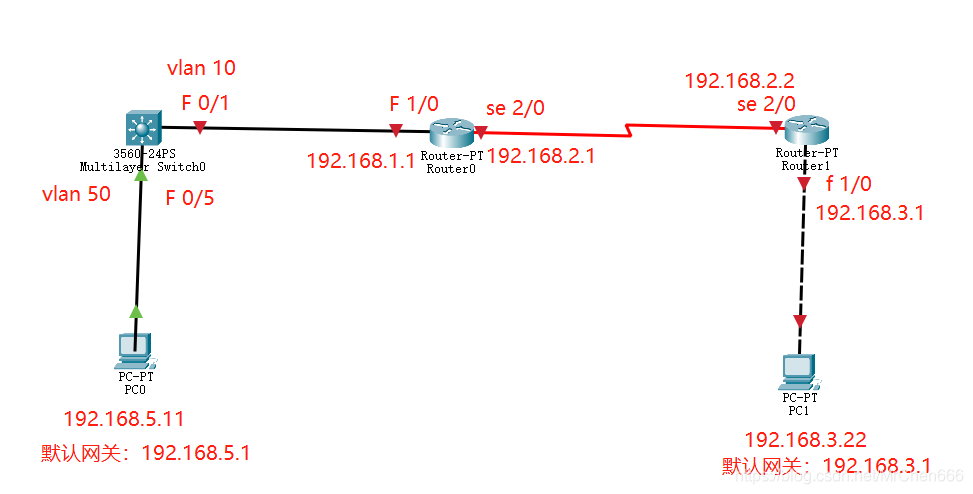
The most detailed network counting experiment in history (2) -- rip experiment of layer 3 switch
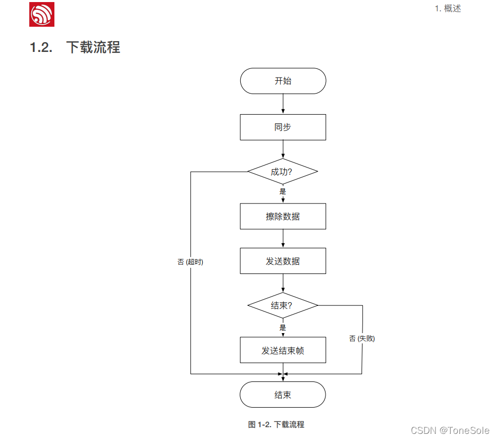
Esp8266 - beginner level Chapter 1
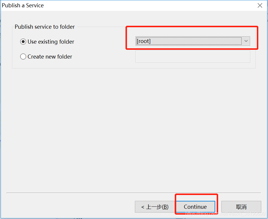
ArcMap publishing slicing service
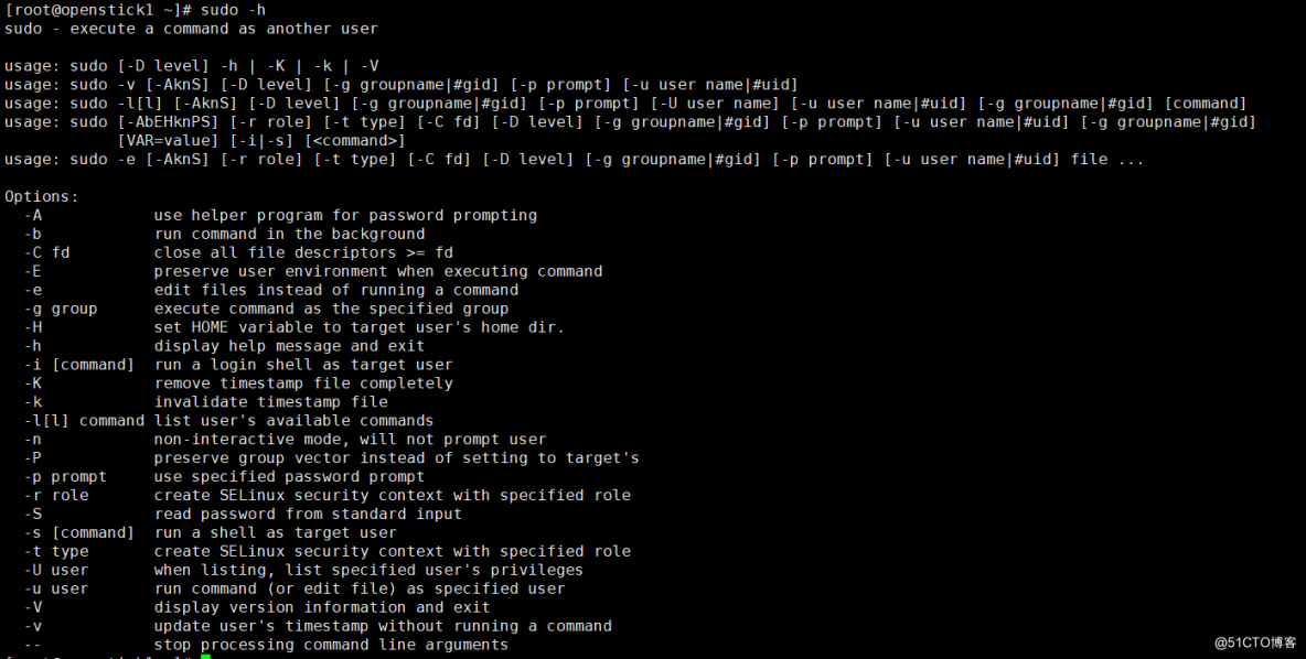
Command - sudo
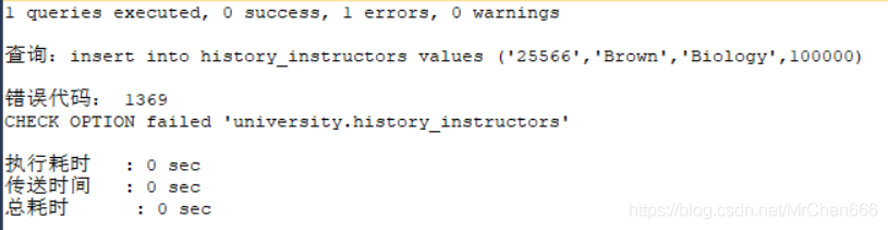
MySQL syntax collation (4)
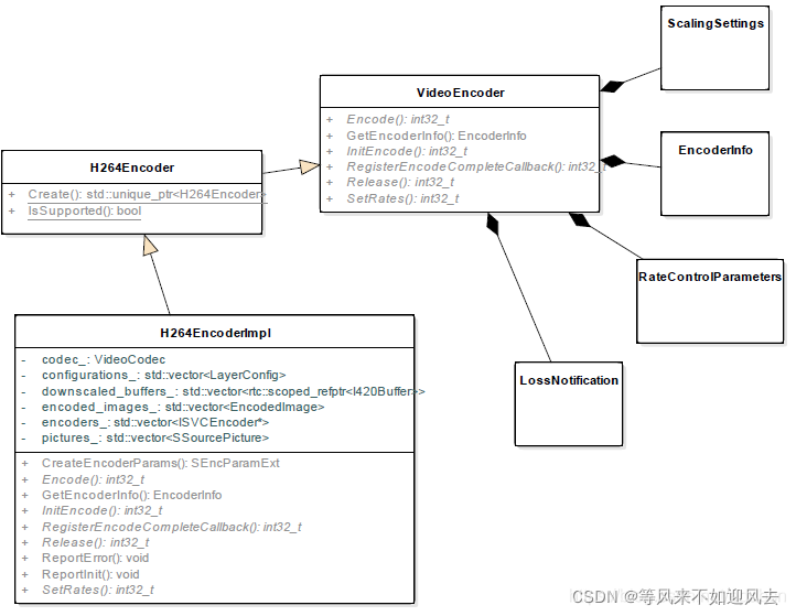
【webrtc】Add x264 encoder for CEF/Chromium

Openharmony open source developer growth plan, looking for new open source forces that change the world!

MySQL syntax collation (2)

Zero base to build profit taking away CPS platform official account
随机推荐
goroutine
Using oes texture + glsurfaceview + JNI to realize player picture processing based on OpenGL es
MySQL数据库 - 单表查询(三)
【webrtc】Add x264 encoder for CEF/Chromium
【h264】libvlc 老版本的 hevc h264 解析,帧率设定
Why is PostgreSQL about to surpass SQL Server?
Speculation on the way to realize the smooth drag preview of video editing software
Openlayers 5.0 loading ArcGIS Server slice service
Web Security
Main differences between go and PHP
MFCC: Mel频率倒谱系数计算感知频率和实际频率转换
arcgis js api dojoConfig配置
OpenHarmony开源开发者成长计划,寻找改变世界的开源新生力!
Codeforces Round #783 (Div. 2) D题解
Steps to build a deep learning environment GPU
arcMap 发布切片服务
ArcMap publishing slicing service
The flyer realizes page Jump through routing routes
Speex Wiener filter and rewriting of hypergeometric distribution
MySQL syntax collation