当前位置:网站首页>Nanodlp v2.2/v3.0 light curing circuit board, connection method of mechanical switch/photoelectric switch/proximity switch and system state level setting
Nanodlp v2.2/v3.0 light curing circuit board, connection method of mechanical switch/photoelectric switch/proximity switch and system state level setting
2022-08-10 12:59:00 【hu5566798】
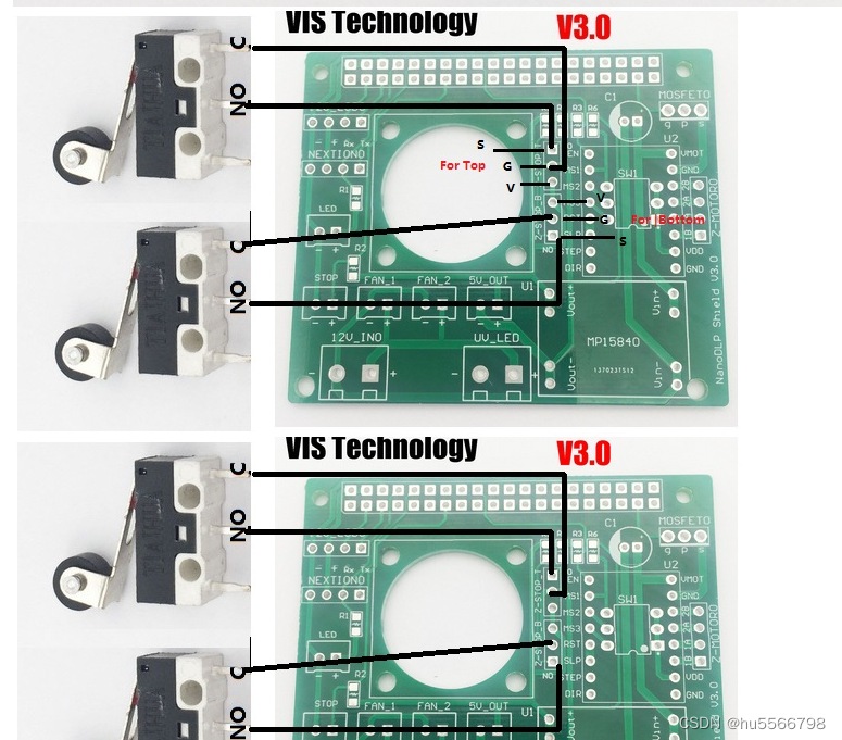
Nanodlp v2.2 limit switch pin diagram S signal, G ground wire, V 5V power supply

Nanodlp v3.0 limit switch pin diagram S signal, G ground wire, V 5V power supply
The principle of ordinary 3d printing accessories photoelectric switch:
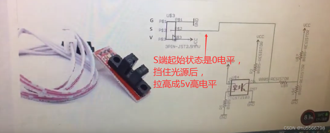
So the corresponding system status level setting should be low level:

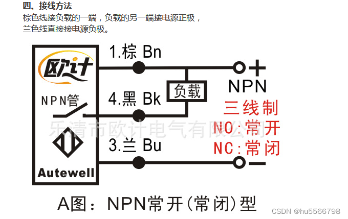
The principle of the mechanical switch on the contrary to the ordinary 3d printing accessories:
The initial non-action state is connected to Vcc in a high-level state, and when the action contacts the NO point, it becomes grounded and becomes a low-level state.

So the corresponding system status level setting should be high level: 
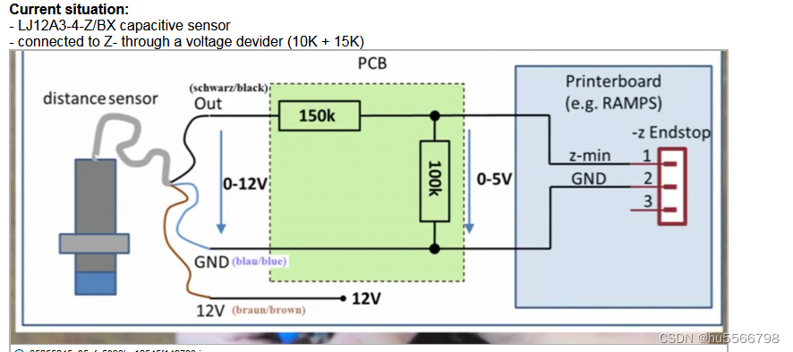
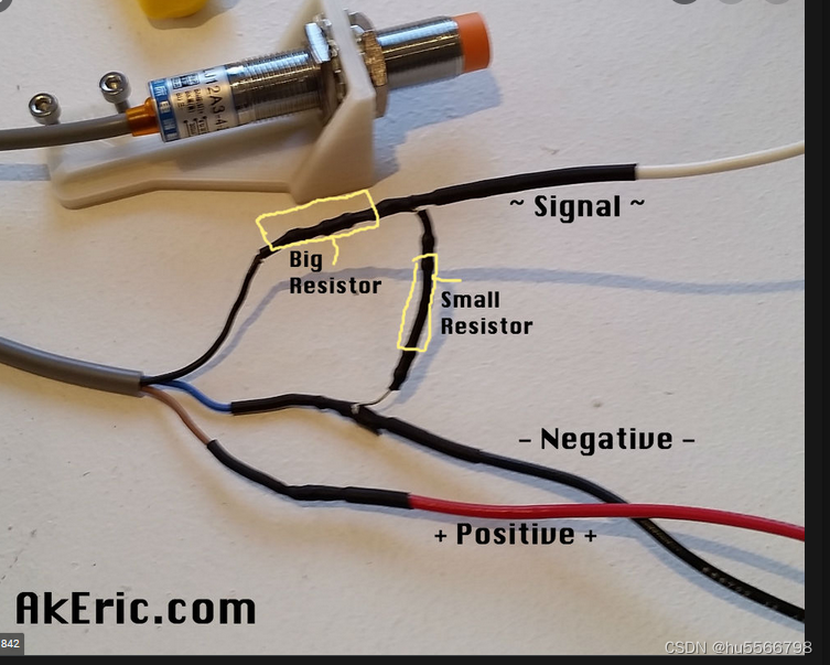
For proximity switches lj12a3-4-z/ex or LJ8A3-4-Z/BX normally open switches, additional auxiliary circuits need to be added to connect to Nanodlp v2.2/v3.0 circuit boards
p>
After connecting to the following auxiliary circuit, the switch is not enabled and defaults to low-level output. Once it is close to the plane, the switch is enabled, and the output terminal is 5v divided and output, and it is in a high-level state.So the use and setting methods are the same as the photoelectric switches
边栏推荐
猜你喜欢

「网络架构」网络代理第一部分: 代理概述

关于flask中static_folder 和 static_url_path参数理解

StarRocks on AWS Review | Data Everywhere Series Event Shenzhen Station ended successfully

Does face attendance choose face comparison 1:1 or face search 1:N?

中科院深圳先进技术院合成所赵国屏院士组2022年招聘启事

AICOCO AI Frontier Promotion (8.10)
MySQL索引的B+树到底有多高?

燃炸!字节跳动成功上岸,只因刷爆LeetCode算法面试题

mSystems | Zhongnong Wang Jie Group Reveals the Mechanisms Affecting Soil "Plastic Interstitial" Microbial Communities

Digicert EV证书签名后出现“证书对于请求用法无效”的解决方案

随机推荐
Highways「建议收藏」
多线程下自旋锁设计基本思想
教育Codeforces轮41(额定Div。2)大肠Tufurama
NodeJs原理 - Stream(二)
吃透Chisel语言.36.Chisel实战之以FIFO为例(一)——FIFO Buffer和Bubble FIFO的Chisel实现
Jiugongge lottery animation
CodeForces - 628D (digital dp)
Loudi Sewage Treatment Plant Laboratory Construction Management
【论文+代码】PEBAL/Pixel-wise Energy-biased Abstention Learning for Anomaly Segmentation on Complex Urban Driving Scenes(复杂城市驾驶场景异常分割的像素级能量偏置弃权学习)
机器学习实战(2)——端到端的机器学习项目
iTextSharp 使用详解
iTextSharp操作PDF
camshift实现目标跟踪
「企业架构」应用架构概述
AICOCO AI Frontier Promotion (8.10)
MYSQL误删数据恢复
sprintboot项目通过interceptor和filter实现接入授权控制
线代 | 秒杀方法与技巧
部署项目半途而废后续
Inventory of Loudi Agricultural Products Inspection Laboratory Construction Guidelines