当前位置:网站首页>Can filter
Can filter
2022-04-23 18:22:00 【Things will turn when they reach the extreme 1024】
CAN filter
1、 Configure the filter so that the filter group works in initialization mode , Enter normal mode after configuration
CAN1->FMR|=1<<0;		// Filter bank 0 Working in initialization mode
//CAN1->FMR|=1<<n; // Filter bank n Working in initialization mode
/*... To configure */
CAN1->FMR&=0<<0;		// Filter bank 0 Enter normal mode
//CAN1->FMR&=0<<n; // Filter bank n Enter normal mode
2、 When configuring a filter, it is also necessary to turn off the activation of the filter
CAN1->FA1R&=~(1<<0);	// filter 0 Do not activate
//CAN1->FA1R&=~(1<<n); // filter n Do not activate

CAN1->FA1R|=1<<0;		// Activate the filter 0
//CAN1->FA1R|=1<<n; // Activate the filter n
3、 Set the filter bit width , Yes 32 Bit and 16 Two modes , This affects the later filtering and shielding ID length
CAN1->FS1R|=1<<0; 		// filter 0 The seat width is 32 position
CAN1->FS1R&=~(1<<0); 		// filter 0 The seat width is 16 position
CAN1->FS1R|=1<<n; 		// filter n The seat width is 32 position
CAN1->FS1R&=~(1<<n); 		// filter n The seat width is 16 position
STID standard ID
EXID Expand ID
IDE
RTR
32 Bit mode
| CAN_FxR1[31:21] | CAN_FxR1[20:3] | CAN_FxR1[2] | CAN_FxR1[1] | CAN_FxR1[0] |
|---|---|---|---|---|
| CAN_FxR2[31:21] | CAN_FxR2[20:3] | CAN_FxR2[2] | CAN_FxR2[1] | CAN_FxR2[0] |
| STID[10:0] | EXID[17:0] | IDE | RTR | 0 |
16 Bit mode
| CAN_FxR1[15:5] | CAN_FxR1[4] | CAN_FxR1[3] | CAN_FxR1[2:0] |
|---|---|---|---|
| CAN_FxR1[31:21] | CAN_FxR1[20] | CAN_FxR1[19] | CAN_FxR1[18:16] |
| CAN_FxR2[15:5] | CAN_FxR2[4] | CAN_FxR2[3] | CAN_FxR2[2:0] |
| CAN_FxR2[31:21] | CAN_FxR2[20] | CAN_FxR2[19] | CAN_FxR2[18:16] |
| STID[10:0] | IDE | RTR | EXID[17:15] |
4、 Set the filter operating mode , Identifier mask bit mode and identifier list mode
CAN1->FM1R&=~(1<<0);		// filter 0 Working in identifier mask bit mode
CAN1->FM1R|=1<<0;		// filter 0 Working in identifier list mode
CAN1->FM1R&=~(1<<n);		// filter n Working in identifier mask bit mode
CAN1->FM1R|=1<<n;		// filter n Working in identifier list mode
5、 Filter associated to FIFOn n=0,1
CAN1->FFA1R&=~(1<<0);		// filter 0 Related to FIFO0
CAN1->FFA1R|=1<<0;		// filter 0 Related to FIFO1
CAN1->FFA1R&=~(1<<n);		// filter n Related to FIFO0
CAN1->FFA1R|=1<<n;		// filter n Related to FIFO1
6、 Set filtering rules
	CAN1->sFilterRegister[0].FR1=0x21<<21;//32 position ID
	CAN1->sFilterRegister[0].FR2=(0x7F<<21);//32 position MASK
Identifier pattern
Each of the registers corresponds to the level of the corresponding bit of the desired identifier .
0: It is expected that the corresponding bit is dominant ;
1: The corresponding bit is expected to be recessive .
Mask bit mode
Each bit of the register indicating whether the corresponding identifier register bit must be consistent with the corresponding bit of the desired identifier .
0: No concern , This bit is not used for comparison ;
1: Must match , The incoming identifier bit must be consistent with the identifier register bit corresponding to the filter
The identifier pattern is FR2 by 1 The bit of identifies the bit to be verified ,FR1 Explain what the identified bit must be , That is, a filter, a rule , The logic here is similar to & operation
	CAN1->sFilterRegister[0].FR1=0x21<<21;//32 position ID
	CAN1->sFilterRegister[0].FR2=(0x7F<<21);//32 position MASK
// Means to check SDID Standard frame ID The lower seven of , The lower seven must be 0x21 To pass
Mask bit mode Is to specify a specific one ID,ID All bits of must conform to the set value
CAN1->sFilterRegister[0].FR1=0x21<<21;//32 position ID
CAN1->sFilterRegister[0].FR2=0xFF<<21)//32 position MASK
// Only 0x00 and 0xFF It can be filtered
Program routine
void CAN_Set_Filter(u8 Addr)
{

	Addr=Addr&0x7F;
	// Filter initialization
	CAN1->FMR|=1<<0;		// The filter group works in initialization mode
/* Filtering rules 1 CAN ID The lower seven digits of must be the same as Addr Agreement , Others don't care  */
	CAN1->FA1R&=~(1<<0);	// filter 0 Do not activate
	CAN1->FS1R|=1<<0; 		// The filter bit width is 32 position .
	CAN1->FM1R|=0<<0;		// filter 0 Working in identifier mask bit mode
	//CAN1->FM1R|=1<<0; // filter 0 Working in identifier list mode
	CAN1->FFA1R|=0<<0;		// filter 0 Related to FIFO0
	CAN1->sFilterRegister[0].FR1=Addr<<21;//32 position ID
	CAN1->sFilterRegister[0].FR2=(0x7F<<21);//32 position MASK
	CAN1->FA1R|=1<<0;		// Activate the filter 0
/* Filtering rules 2 CAN ID Of the 7 Bit must be 1, That is, only 0x80 Can pass */
	CAN1->FA1R&=~(1<<1);	// filter 1 Do not activate
	CAN1->FS1R|=1<<1; 		// filter 1 The seat width is 32 position .
	//AN1->FM1R|=0<<1; // filter 1 Working in identifier mask bit mode
	CAN1->FM1R|=1<<1;		// filter 1 Working in identifier list mode
	CAN1->FFA1R|=0<<1;		// filter 1 Related to FIFO0
	CAN1->sFilterRegister[1].FR1=0x80<<21;//32 position ID
	CAN1->sFilterRegister[1].FR2=(0x80<<21);//32 position MASK
	CAN1->FA1R|=1<<1;		// Activate the filter 1
/* Filtering rules 3 CAN ID The lower eight digits of must be 0x00*/
	CAN1->FA1R&=~(1<<2);	// filter 2 Do not activate
	CAN1->FS1R|=1<<2; 		// filter 2 The seat width is 32 position .
	CAN1->FM1R|=0<<2;		// filter 2 Working in identifier mask bit mode
	//CAN1->FM1R|=1<<2; // filter 2 Working in identifier list mode
	CAN1->FFA1R|=0<<2;		// filter 2 Related to FIFO0
	CAN1->sFilterRegister[2].FR1=0x00<<21;//32 position ID
	CAN1->sFilterRegister[2].FR2=(0xFF<<21);//32 position MASK
	CAN1->FA1R|=1<<2;		// Activate the filter 2

	CAN1->FMR&=0<<0;		// The filter bank enters normal mode
}
版权声明
本文为[Things will turn when they reach the extreme 1024]所创,转载请带上原文链接,感谢
https://yzsam.com/2022/04/202204210610057105.html
边栏推荐
- What are the relationships and differences between threads and processes
- Selenium + webdriver + chrome realize Baidu to search for pictures
- Daily CISSP certification common mistakes (April 15, 2022)
- Multi thread crawling Marco Polo network supplier data
- Matlab tips (6) comparison of seven filtering methods
- If condition judgment in shell language
- Gst-launch-1.0 usage notes
- Daily CISSP certification common mistakes (April 13, 2022)
- Nodejs installation
- CISSP certified daily knowledge points (April 12, 2022)
猜你喜欢
函数递归以及趣味问题的解决
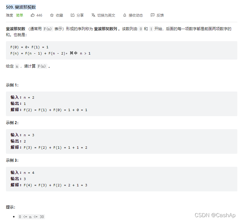
【ACM】509. Fibonacci number (DP Trilogy)

Spark performance optimization guide

Robocode tutorial 3 - Robo machine analysis
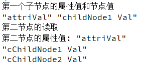
Qt读写XML文件(含源码+注释)

Installation du docker redis
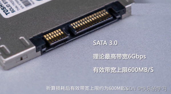
SSD硬盘SATA接口和M.2接口区别(详细)总结
QT add external font ttf
解决允许在postman中写入注释请求接口方法

ArcGIS table to excel exceeds the upper limit, conversion failed
随机推荐
Win1远程出现“这可能是由于credssp加密oracle修正”解决办法
How to restore MySQL database after win10 system is reinstalled (mysql-8.0.26-winx64. Zip)
SSD硬盘SATA接口和M.2接口区别(详细)总结
【ACM】376. 摆动序列
If condition judgment in shell language
Daily CISSP certification common mistakes (April 15, 2022)
xlsxwriter. exceptions. Filecreateerror: [errno 13] permission denied
Rust: the output information of println is displayed during the unit test
NVIDIA Jetson: GStreamer and openmax (GST OMX) plug-ins
Install pyshp Library
Queue solving Joseph problem
How to install jsonpath package
Docker 安装 MySQL
Daily CISSP certification common mistakes (April 12, 2022)
RC smart pointer in rust
Const keyword, variable and function are decorated with const
Stm32mp157 wm8960 audio driver debugging notes
Reptile efficiency improvement method
Refcell in rust
Pointers in rust: box, RC, cell, refcell