当前位置:网站首页>Communication between RING3 and ring0
Communication between RING3 and ring0
2022-04-23 20:38:00 【Cambridge art student】
One 、IRP Three kinds of buffers
By looking at IRP Structure information of , We found that there are three ways to describe buffers , For different IO Category , The way the buffer is written is also different , As shown below :
| AssociatedIrp.SystemBuffer | It is generally used for solutions that are relatively simple and do not pursue efficiency hold R3 The buffered data in memory in the layer is copied to kernel space . Be careful , Direct copy . |
|---|---|
| MdlAddress | By construction MDL Can achieve this R3 To R0 Address mapping function .MDL Can be translated as " Memory descriptor chain ", It's essentially a pointer , From this MDL You can read out a virtual address of the kernel space . That makes up for UserBuffer Deficiency , Simultaneous ratio SystemBuffer The full copy method should be lightweight , Because there is actually no copy of this memory , Still in place . |
| UserBuffer | Ring3 The buffer address of is placed directly in UserBuffer in , Access directly in kernel space ( Efficient ). It should be noted that , When the current process is consistent with the sending process , The kernel can access the memory space of the application layer . One Once the kernel process has switched , This visit is over ( The context of the process has switched , Due to kernel space sharing , After switching, the corresponding contents of the same address are different ). |
    char *Buffer = NULL;

    if (Irp->AssociatedIrp.SystemBuffer)
        Buffer = Irp->AssociatedIrp.SystemBuffer;
    else if (Irp->MdlAddress)                // MmGetSystemAddressForMdlSafe Is a macro , It's for MDL The described buffer returns a non paged system space virtual address .
        Buffer = MmGetSystemAddressForMdlSafe(Irp->MdlAddress, NormalPagePriority);
    else if (Irp->UserBuffer)
        Buffer = Irp->UserBuffer;
}
During memory access ,IRP The three buffers correspond to three different read and write modes :
1、AssociatedIrp.SystemBuffer->DO_BUFFERED_IO:I/O The manager first creates a system buffer equal to the size of the user mode data buffer . And your driver will use this system buffer to work .I/O The manager is responsible for copying data between the system buffer and the user mode buffer .( Be careful , Direct copy )
2、MdlAddress->DO_DIRECT_IO:I/O The manager locks the physical memory page that contains the user mode buffer , And create one called MDL( Memory descriptor table ) Auxiliary data structure to describe the locked page . So your driver will use MDL Work .
3、UserBuffer->NEITHER(0):I/O The manager simply passes the virtual address of the user mode to you .
When we created the device , You should specify how to read and write the buffer
The above code can be used as a way to read and write buffer , It can also be done through DeviceObject Medium Falg Bit to control the read and write mode of the buffer .
NTSTATUS AddDevice(DriverObject, PhysicalDeviceObject)
{

    PDEVICE_OBJECT dec;
    IoCreateDevice(..., &dec);
    dec->Flags |= DO_BUFFERED_IO;
    //buffer or direct
    dec->Flags |= DO_DIRECT_IO;
    //neither
    dec->Flags |= 0;
}
Two 、I/O Equipment control
There are four ways to transfer buffer data , By different means of transmission ,IO Equipment control 3 Circumferentially 0 The data of the ring is written and read , They are respectively defined as
#define METHOD_BUFFERED 0
#define METHOD_IN_DIRECT 1
#define METHOD_OUT_DIRECT 2
#define METHOD_NEITHER 3
Two kinds of DIRECT The difference between : Open the device with read-only permission ,METHOD_IN_DIRECT Of IOCTL Successful operation , and METHOD_OUT_DIRECT Of IOCTL operation failed ; Open device with read-write permission ,METHOD_IN_DIRECT And METHOD_OUT_DIRECT Of IOCTL Operation succeeded
switch (IoControlCode)
	{

	case IOCTL_GET_EVENT_DATA:
	{

		if (OutputBufferLength == sizeof(USER_EVENT_DATA))
		{

			PEVENT_DATA EventData;
			LARGE_INTEGER Timeout;

			Timeout.QuadPart = -3LL * 1000LL * 1000LL * 10LL;	//
			EventData = KenPopEventData(&Timeout);
            // Take out the information in the linked list
			if (EventData) {

				KenBuildUserEventData(EventData, (PUSER_EVENT_DATA)Irp->AssociatedIrp.SystemBuffer);
				// Here is to transfer user data to Ring0 layer

				Irp->IoStatus.Information = sizeof(USER_EVENT_DATA);
				Irp->IoStatus.Status = STATUS_SUCCESS;
			}
		}
		break;
		//............
	}
In order to achieve Ring3 And Ring0 Interaction , Set up the only 32 Bit system I/O Control code , adopt Ring3 layer DeviceIoControl To achieve communication . Above IOCTL_GET_EVENT_DATA By CTL_CODE give , The first parameter is the equipment type (FILE_DEVICE_UNKNOWN); The second parameter defines the function code in the equipment category ,0-2047 Reserved for Microsoft , No more than 4095; The third parameter is IO Four ways to control the transfer of buffer data ; The fourth parameter is permission (FILE_READ_DATA).
#define CTL_CODE( DeviceType, Function, Method, Access ) (((DeviceType) << 16) | ((Access) << 14) | ((Function) << 2) | (Method))
3、 ... and 、Ring3 And Ring0 Communication for
After the above analysis ,Ring3 And Ring0 Communication can be understood as , The driver first determines the buffer read and write mode , Driver and application customization IO Control code , And then call DeviceIoControl function ,IO The manager will generate a MajorFunction by IRP_MJ_DEVICE_CONTROL(DeviceIoControl The function produces this IRP), adopt Ring3 Layer control code , Drive response to make corresponding judgment . To complete the Ring3 And Ring0 Communication for . For example, we use METHOD_BUFFERED, It means that the system passes the user's input and output through pIrp->AssociatedIrp.SystemBuffer To buffer , So this way of communication is more secure .
summary
1、 The device object sets the buffer read / write mode , Drivers and applications pass CTL_CODE Macro customization is good IO Control code , Specifies how buffer data is passed .
2、Ring0 Layer definition driver device name , Symbolic link name , Associate symbolic link names with device object names , wait for IO Control code (IoCreateDevice,IoCreateSymbolicLink).
3、Ring3 Layers are represented by symbolic link names CreateFile Function to get the device handle DeviceHandle, Re pass DeviceIoControl Send the control code to the dispatch function through the device handle to complete the communication .
Reference blog :https://www.cnblogs.com/LittleHann/p/3450436.html
版权声明
本文为[Cambridge art student]所创,转载请带上原文链接,感谢
https://yzsam.com/2022/04/202204210546556569.html
边栏推荐
- 上海回應“面粉官網是非法網站”:疏於運維被“黑”,警方已立案
- Tensorflow 2 basic operation dictionary
- [matlab 2016 use mex command to find editor visual studio 2019]
- [SQL] string series 2: split a string into multiple lines according to specific characters
- Resolve the error - error identifier 'attr_ id‘ is not in camel case camelcase
- Use of node template engine
- Learn to C language fourth day
- Latex formula
- 三十.什么是vm和vc?
- bounding box iou
猜你喜欢
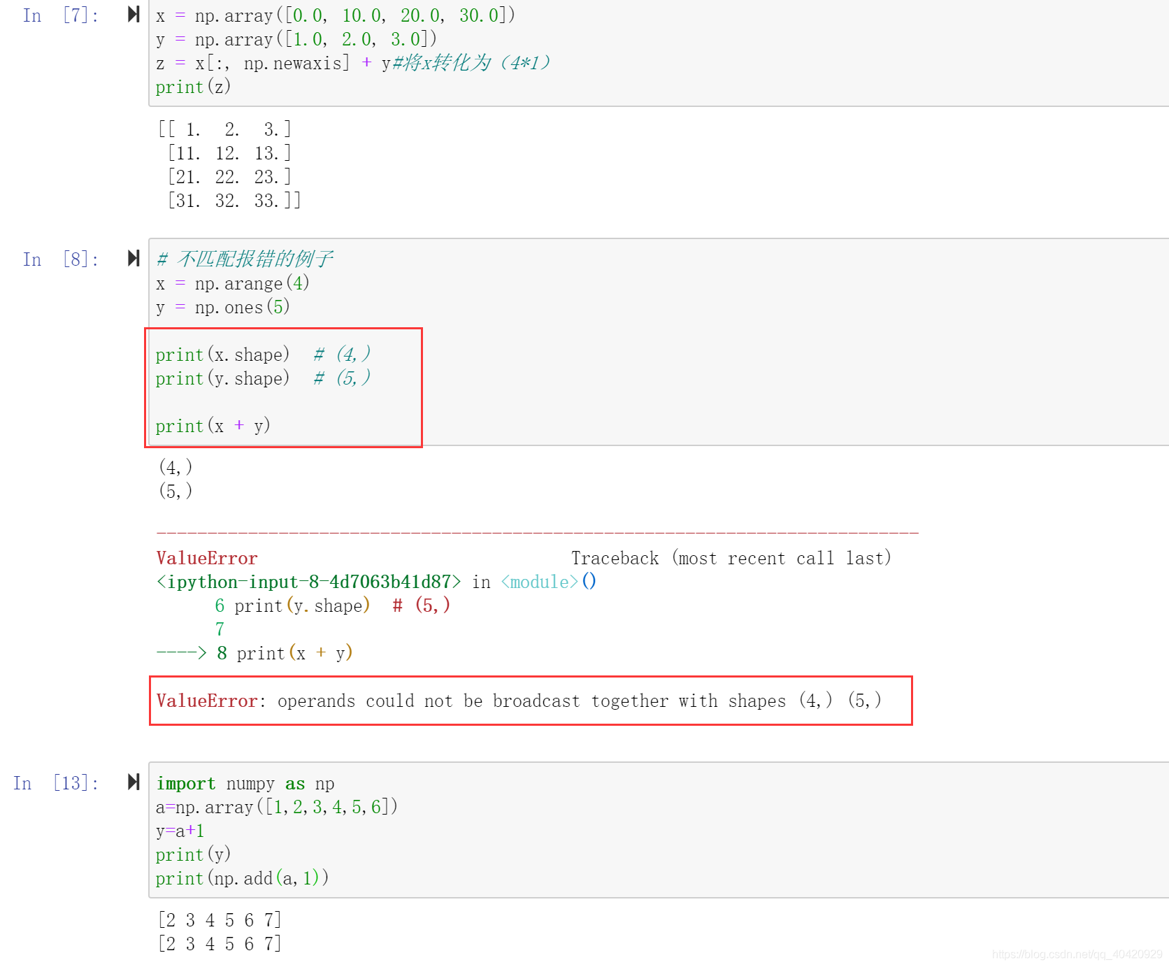
Numpy mathematical function & logical function
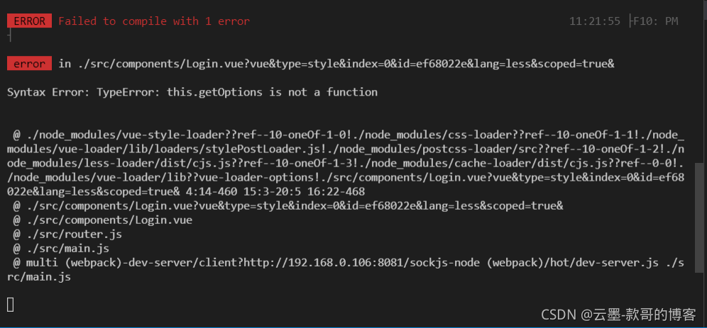
Syntax Error: TypeError: this. getOptions is not a function
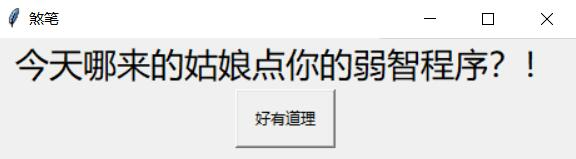
A useless confession artifact
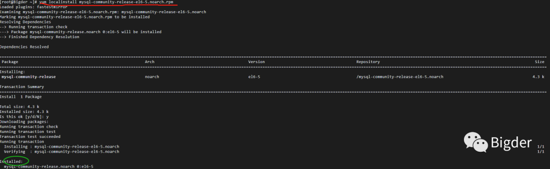
Install MySQL 5.0 under Linux 64bit 6 - the root password cannot be modified
![[PTA] l1-002 printing hourglass](/img/9e/dc715f7debf7edb7a40e9ecfa69cef.png)
[PTA] l1-002 printing hourglass
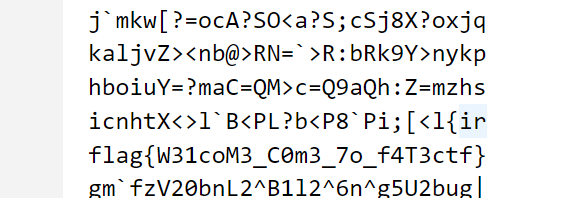
2022dasctf APR x fat epidemic prevention challenge crypto easy_ real
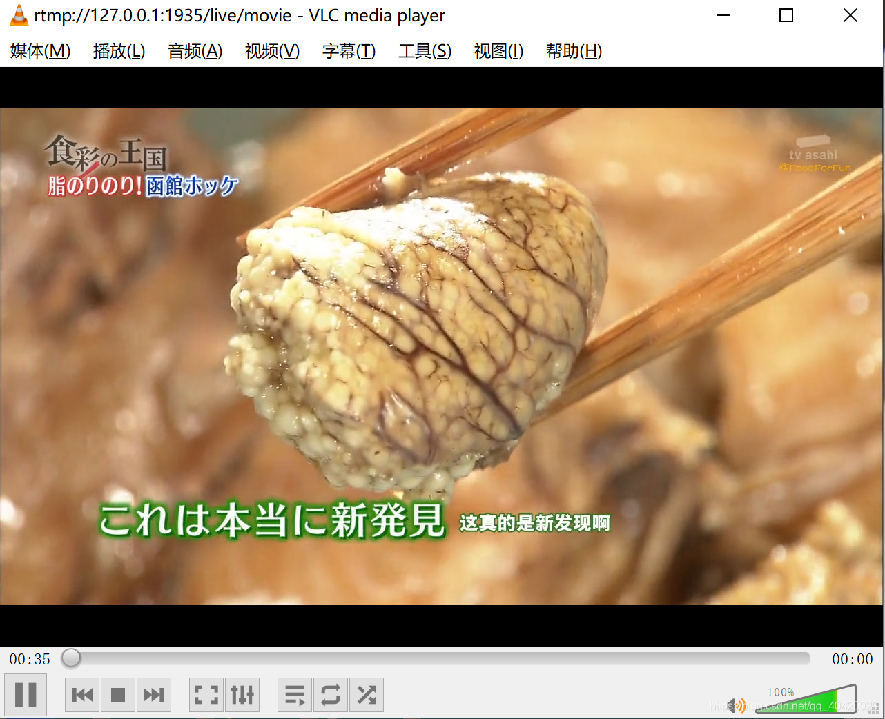
Livego + ffmpeg + RTMP + flvjs to realize live video
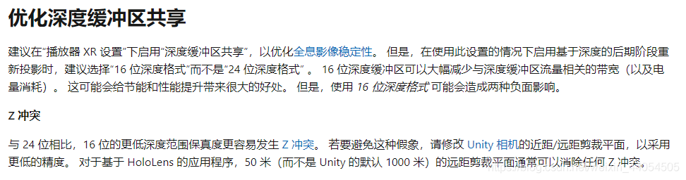
Unity solves Z-fighting
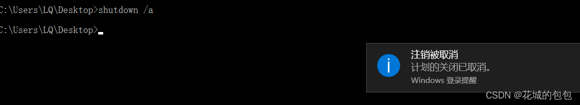
DOS command of Intranet penetration
Case of the third day of go language development fresh every day project - news release system II
随机推荐
LeetCode 116. Populate the next right node pointer for each node
bounding box iou
Leetcode 74. Search two-dimensional matrix
[graph theory brush question-4] force deduction 778 Swimming in a rising pool
BMP JPEG picture to vector image contourtrace
2022dasctf APR x fat epidemic prevention challenge crypto easy_ real
Implementation of mypromise
vulnhub DC:1渗透笔记
On BIM data redundancy theory
内网渗透之DOS命令
LeetCode 74、搜索二维矩阵
ArcGIS js api 4. X submergence analysis and water submergence analysis
DOS command of Intranet penetration
上海回应“面粉官网是非法网站”:疏于运维被“黑”,警方已立案
Recognition of high-speed road signs by Matlab using alexnet
Scripy tutorial - (2) write a simple crawler
Preliminary understanding of cache elimination algorithm (LRU and LFU)
GO语言开发天天生鲜项目第三天 案例-新闻发布系统二
Vscode download speed up
CONDA environment management command