当前位置:网站首页>TLC5615 based multi-channel adjustable CNC DC regulated power supply, 51 single chip microcomputer, including proteus simulation and C code
TLC5615 based multi-channel adjustable CNC DC regulated power supply, 51 single chip microcomputer, including proteus simulation and C code
2022-04-23 14:24:00 【Jiang Yuzhi】
The design requirements
- 5V Single power supply operation ;
- The voltage output range is the reference input voltage 2 times , The adjustment range of this design is :0V~3.9V;
- The voltage adjustment accuracy is up to 0.02%;
- Two voltage regulation methods : Automatic mode and manual mode ;
- 3 Circuit voltage output channel , And can be controlled separately ;
- When the voltage exceeds the set range , automatic alarm ;
TLC5615 brief introduction
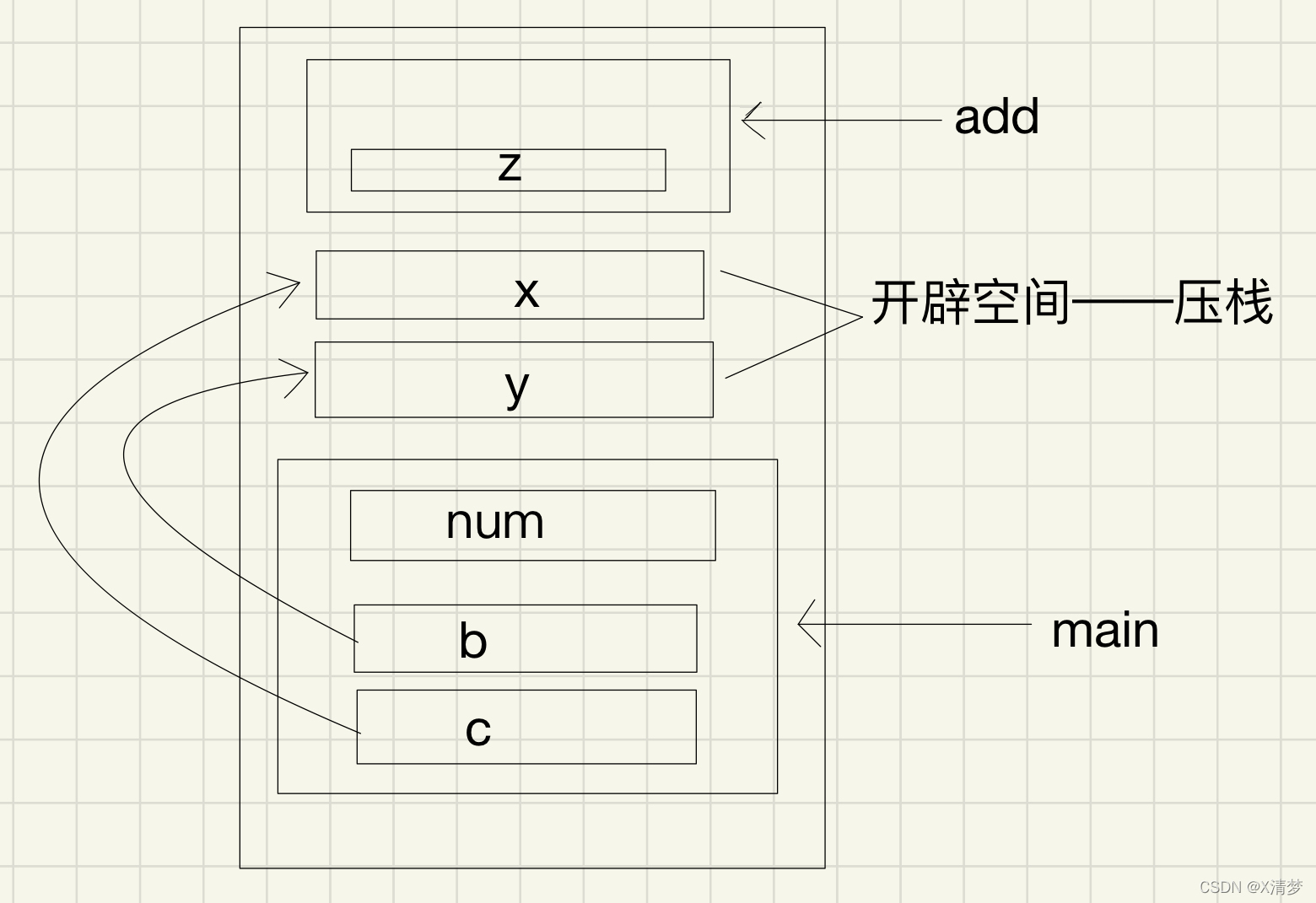
TLC5615 Is a reference input with buffer ( High impedance ) Of 10 Bit voltage output digital - Analog converter (DAC),DAC It has an output voltage range of twice the reference voltage , And DAC It's monotonous . The device is simple to use , Use single 5V Power operation .
![Reference voltage VREFIN = VCC * [ R8/(R7+R8) ]](/img/a9/cf2a6292ae06ed279c1f18e30295bf.jpg)
Reference voltage VREFIN = VCC * [ R8/(R7+R8) ]
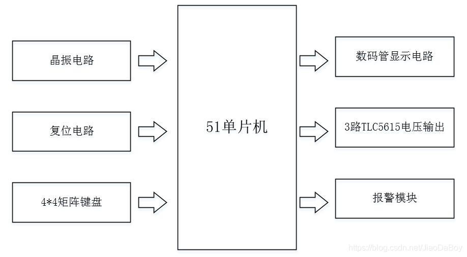
System Overview
Multi channel adjustable TLC5615 The NC DC power supply is provided by 51 Minimum system of single chip microcomputer ,3 road TLC5615 Voltage digital to analog conversion circuit 、 Digital tube display module 、4*4 Matrix keyboard and alarm module .
Automatic mode
MCU control 3 Circuit DC voltage output , The nixie tube displays the current number of channels and the output voltage value of the channel in real time , Press the key to control the switching of the number of channels and the setting of voltage , The alarm module monitors whether the output voltage exceeds the maximum set value (3.9V).
After the numerical quantity is input through the matrix keyboard , the TLC5615 Digital to analog chip conversion , Output analog DC voltage , The voltage adjustment range is 0.1V.
When the set value is greater than 3.9V when , Alarm module LED The light is on , At the same time, nixie tube display 0.0, Prompt to modify the input value again .
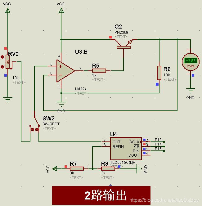
Manual mode
Switch a certain circuit SW Hit to the left , The output of this voltage is controlled by the sliding rheostat .
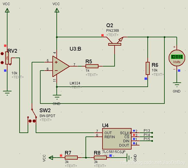
In manual mode , The voltage output is no longer affected 51 Single chip microcomputer 、 Digital to analog conversion chip and matrix keyboard control . The whole voltage output circuit consists of a sliding rheostat 、 Operational amplifiers and PNP Triode composition .
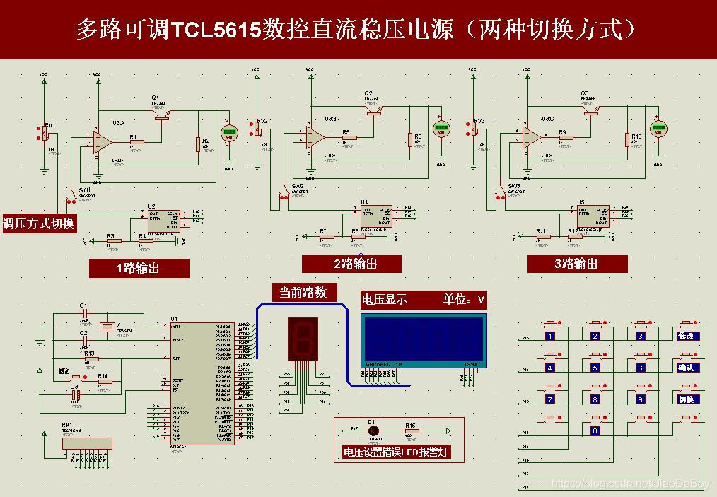
System simulation circuit diagram

Analysis of simulation results
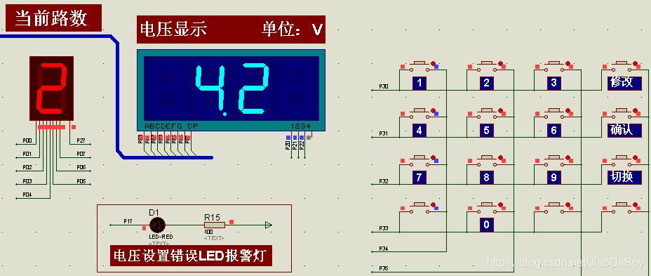
- Through the matrix keyboard , Set the first 2 The output voltage of the channel is 2.8V, give the result as follows .
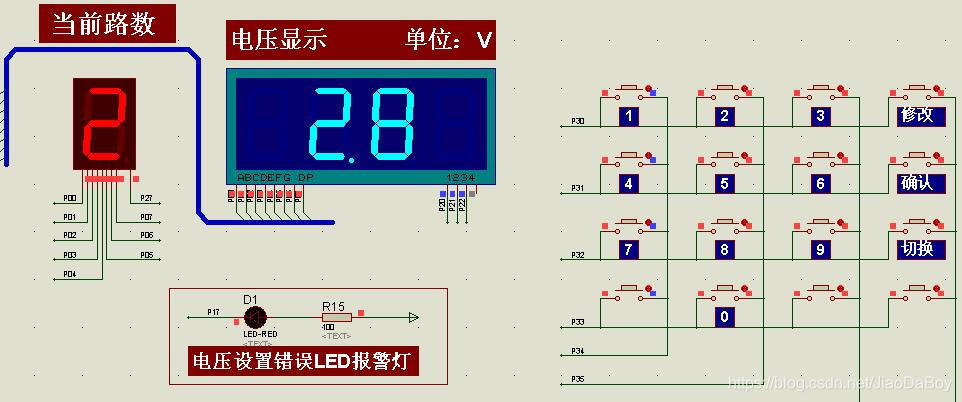
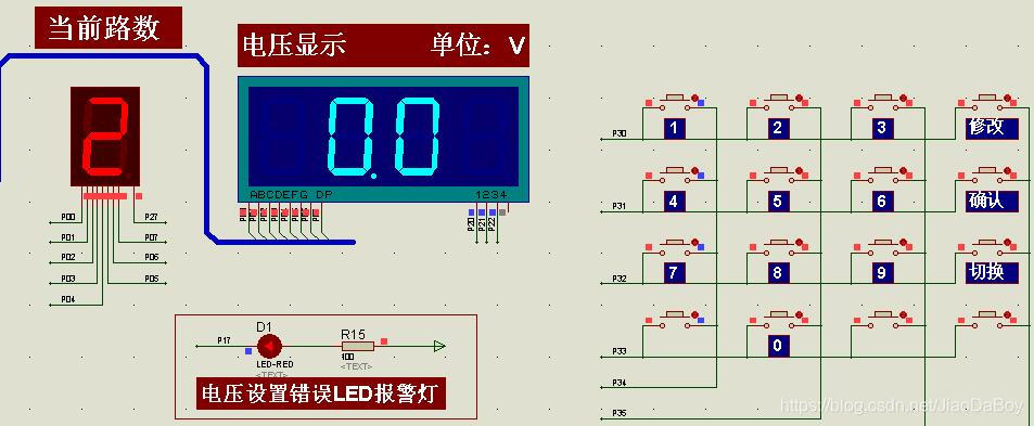
- When the keyboard sets the voltage output value to 4.2V( Greater than 3.9V) when , Press the OK key , The nixie tube shows 0.0,LED The warning lamp is on , The actual voltage output is 0.02V≈0V.
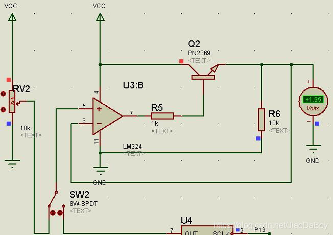
- Click on SW2, Turn the switch to the left , At this time, the output of voltage is controlled by sliding rheostat , No longer controlled by single chip microcomputer , In this example, the output voltage is 1.95V.
part C Code
void main(void)				 // The main program
{

// timer0_init(); // Initialize the timer 0
	while(1)
	{

		key_scan();			// Call keyboard scan function
		TLC5615_DA_1(val_1);	// Process the value sent by the keyboard
		TLC5615_DA_2(val_2);
		TLC5615_DA_3(val_3);
		switch(choice_flag)
		{

			case 1 : display(Vol_1+num_1-1);	break;
			case 2 : display(Vol_2+num_2-1);	break;
			case 3 : display(Vol_3+num_3-1);	break;
		}


	}
}

void timer0_isr(void)  interrupt 1       	// timer0 Interrupt service function
{

                         					// Bit selection variable of nixie tube
	TR0 = 0;                       		 	// Stop count
	TL0 = (65536-5000)%256;					// Reload counter initial value
	TH0 = (65536-5000)/256;
                              	// Bit cyclic variable plus 1
	if(cp >= 4)
		cp = 0;
	switch(choice_flag)
	{

		case 1:    deal(val_1);break;
		case 2 :   deal(val_2);break;
		case 3:    deal(val_3);break;
	}

// deal(5698); // Cycle show 1 Time ,j Zero clearing
   	TR0 = 1;
// deal(val_1);
// delay(100);
	P0=0xff;  // And j Corresponding ,P2 Output bit selection signal of nixie tube
	switch(cp)
	{

		case 0: P0 = 0xc1;break;
		case 1: P0 = LED[shi];break;
		case 2: P0 = LED[bai]&0x7f;break;
// case 3: P0 = 0xbf;break;
		case 3: P0 = LED[choice_flag];break;
	}
	P2 = Bit_sel[cp];
	cp++;
}
The shared resources are
(1)C Program ;
(2)Proteus Simulation file ;
(3)TLC5615 Chip manual ;
(4) Program design flow chart ;
The full set of resources is as follows
Get multi-channel adjustable TLC5615 Design of NC DC regulated power supply system ,Proteus Simulation 、C Program 、Visio flow chart 、TLC5615 Wait for references .
WeChat search for my official account : Jiaoyuan Xiaozhi
版权声明
本文为[Jiang Yuzhi]所创,转载请带上原文链接,感谢
https://yzsam.com/2022/04/202204231412472243.html
边栏推荐
猜你喜欢
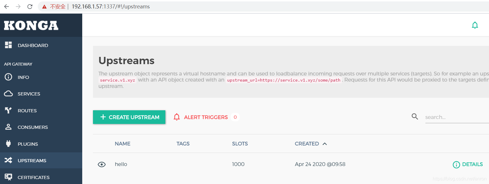
API Gateway/API 网关(二) - Kong的使用 - 负载均衡Loadbalance
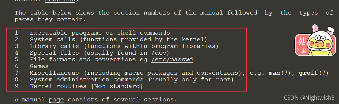
man man随记和crontab的@reboot用法
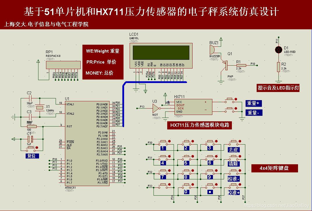
电子秤称重系统设计,HX711压力传感器,51单片机(Proteus仿真、C程序、原理图、论文等全套资料)

如何5分钟上手使用OCR
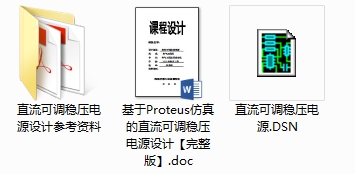
直流可调稳压电源的Proteus仿真设计(附仿真+论文等资料)

51单片机+LCD12864液晶显示的俄罗斯方块游戏,Proteus仿真、AD原理图、代码、论文等
c语言在结构体传参时参数压栈问题
Man man notes and @ reboot usage of crontab
Nacos作为配置中心(四) 使用Demo
KVM learning resources
随机推荐
Qt实战:云曦聊天室篇
AT89C51单片机的数字电压表开发,量程0~5V,proteus仿真,原理图PCB和C程序等
八路抢答器系统51单片机设计【附Proteus仿真、C程序、原理图及PCB文件、元器件清单和论文等】
Man man notes and @ reboot usage of crontab
关于在vs中使用scanf不安全的问题
Flop effect
LM317的直流可调稳压电源Multisim仿真设计(附仿真+论文+参考资料)
Visio画拓扑图随记
OpenSSH的升级、版本号的修改
矩阵交换行列
Nacos作为配置中心(四) 使用Demo
gif转为静态图片处理
Upgrade of openssh and modification of version number
A table splitting implementation scheme of MySQL and InnoDB, MyISAM and MRG_ Introduction to MyISAM and other engine application scenarios
初始c语言大致框架适合复习和初步认识
Use cases of the arrays class
API Gateway/API 网关(三) - Kong的使用 - 限流rate limiting(redis)
流程控制之分支语句
Use of ansible and common modules
KVM学习资源