当前位置:网站首页>[Building a 2D rasterized map using SLAM technology]
[Building a 2D rasterized map using SLAM technology]
2022-08-11 10:10:00 【2345VOR】
应用SLAMtechnology to build two-dimensional rasterized map
一、 设计目标
学习常见的SLAM知识,使用Cartographer算法实现二维栅格化地图的建立,并进行优化和测试.
二、 技术要求
查找建图相关资料,了解常用的激光SLAM算法;
安装Linux系统,建议Ubuntu18.04;
安装ROS环境并学习其基本操作;
完成谷歌Cartographer算法建图环境搭建;
使用Cartagrapher算法进行建图测试;
学习算法原理,对算法进行优化及测试.
三、 设计方案
1. 激光SLAM简介
SLAM (simultaneous localization and mapping) , 即时定位与地图构建,or concurrent mapping and positioning.问题可以描述为:将一个机器人放入未知环境中的未知位置,是否有办法让机器人一边移动一边逐步描绘出此环境完全的地图,所谓完全的地图(a consistent map)是指不受障碍行进到房间可进入的每个角落.近年来,Intelligent robot technology is developing rapidly around the world.from indoors、Outer handling robot,到自动驾驶汽车,to aerial drones、Underwater detection robot, etc.,The application of intelligent robot got great breakthrough.
Lidar has been shown to work in low light、More effective in environments with less texture, etc.,Can provide observational data with high signal-to-noise ratio,精度高,测量距离远,The three-dimensional information of the target can be accurately obtained.激光SLAM技术相对成熟,在工业 AGV、The field of unmanned driving has been widely used.
激光SLAMUse a 2D laser rangefinder or a 3D laser rangefinder to perceive the scene,Estimate the motion of the vehicle using the returned point cloud data,and output the result of scene modeling.激光SLAMThe working principle can also be divided into front-end and back-end2个部分,The front end is used to obtain scanned data,Estimating the motion relationship of vehicles by matching point clouds between frames,The backend is used to perform optimization calculations,Loop closure detection and output of scene modeling, etc..in front-end computing,Commonly used point cloud matching methods include iterative nearest neighbors.(Iterative Closest Point, ICP)Algorithms and their variants,如PI-IC,Correlation scan matching method (Correlation Scan Match, CSM),特征匹配法[8]and gradient optimization methods, etc.,in the backend optimization method,Commonly used methods include filter-based methods and graph-based optimization methods, etc..目前常见 的 二 维 激 光SLAM方 法 有:Gmapping-SLAM, Hector-SLAM,Karto SLAM和 Cartographer等,三 维 激 光SLAM方 法有LOAM,LeGO-LOAM和 MC2SLAM等.This time we mainly use Google's open sourceCartographerMapping algorithm for related algorithm testing and improvement.
2. Cartographer简介与使用
1) Cartographer简介
2016年10月5日,Google announced the opening of a newcartographer's real-time location and map modeling library,Developers can use this library to implement robot positioning and mapping functions in 2D or 3D.cartograhperis designed to be used when computing resources are limited,Real-time acquisition of relatively high-precision2D地图.Considering that the particle filter method based on the simulation strategy has a high demand for memory and computing resources in a larger environment,cartographerUsing a graph network-based optimization method.目前cartographer主要基于激光雷达来实现SLAM,Google hopes to support more sensor and robotics platforms through subsequent development and community contributions,At the same time, new functions are continuously added.
The first is the installation process of the entire feature packcartographerFeature packs have been linked withROS集成,Binary packages are now available,This time, the source code compilation method is used to install.In order not to conflict with existing function packages,最好为cartographer专门创建一个工作空间,Here we create a new workspacegoogle_ws,Then use the following steps to download the source code and complete the compilation.
- 安装工具 You can use the following command to install tools:
$ sudo apt-get update
$ sudo apt-get install -y python-wstool python-rosdep ninja-build
- 初始化工作空间 Initialize the workspace with the following command:
$ cd google_ws
$ wstool init src
- 加入cartographer_ros.rosinstalland update dependencies 命令如下:
$ wstool merge -t src https://raw.githubusercontent.com/googlecartographer/cartographer_ros/master/cartographer_ros.rosinstall
$ wstool update -t src
- 安装依赖并下载cartographer相关功能包 命令如下:
$ rosdep update
$ rosdep install --from-paths src --ignore-src --rosdistro=${ROS_DISTRO} -y
- 编译并安装 命令如下
$ catkin_make_isolated --install --use-ninja
$ source install_isolated/setup.bash
If the download server cannot be connected,You can also use the following command to modifyceres-solver源码的下载地址为
https://github.com/ceres-solver/ceres-solver.git
$ gedit google_ws/src/.rosinstall
After the change is complete, re-run the command to compile and install,如果没有出错,则cartographerThe related function packs of the installed successfully.
2) 官方demo的演示
首先,下载官方提供的2D Cartographer功能包,Reproduce and test the operation of the feature pack.
$ wget -P ~/Downloads https://storage.googleapis.com/cartographer-public-data/bags/backpack_2d/cartographer_paper_deutsches_museum.bag
接着,运行Cartographer的demo文件,Reproduce the mapping function of the file.如下图3-1、3-2所示:
$ roslaunch cartographer_ros demo_backpack_2d.launch bag_filename:=${
    HOME}/Downloads/cartographer_paper_deutsches_museum.bag
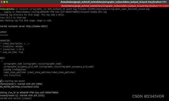
图3-1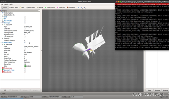
图3-2
另起终端,输入下列指令,如图3-3View subscribed topics in this mapping function:
$ rostopic list
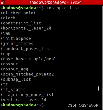
图3-3
另起一个终端,View this projecttf配置,如下图3-4所示:
$ rosrun rqt_tf_tree rqt_tf_tree

图3-5
另起终端,输入下列指令,View the relevant nodes where the mapping function is running,如图3-5所示:
$ rosrun rqt_graph rqt_graph
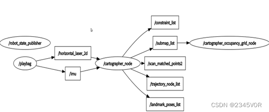
图3-5
3. Ackerman model test
Reproduce the function of the official function pack,we can learn betterCartographer与传统2DAdvantages, disadvantages and similarities and differences of mapping algorithms.So we put the first part of the five key tasks inrosThe Ackerman motion model built in,By configuring its related parameters,make him availableCartographerTest related mapping and navigation functions in a simulation environment,Deepen Your Understanding of the Ackermann Movement, Part 1,also strengthenCartographerActual Mapping Effect in Ackerman Movement.
1) SLAM建图
首先,need to googleCartographerBuilt in figure feature pack configure some related data,Since the common use is basically2D或者3D激光雷达,as my bot uses2D激光,Here is an introduction to this,We need to do three things to transplant into our own robot:
第一件:一定要把Cartography和自己ROS Work space isolated,不然存在问题,Both are not made with the same compiler.
第二件:更改demo_revo_lds.launchmake it match your bot
第三件:Configured according to your robotTF结构对cartography的配置文件进行更改,Major changes herelua脚本,这里使用revo_lds.lua.
更改demo_revo_lds.launch,The main deletion here is that no configuration is required,如跑bagof nodes and changes to our own published2D激光雷达的数据,Changed as follows:
<launch>
  <param name="/use_sim_time" value="false" />

  <node name="cartographer_node" pkg="cartographer_ros" type="cartographer_node" args=" -configuration_directory $(find cartographer_ros)/configuration_files -configuration_basename revo_lds.lua" output="screen">
    <remap from="scan" to="scan" />
  </node>
  <node name="cartographer_occupancy_grid_node" pkg="cartographer_ros" type="cartographer_occupancy_grid_node" args="-resolution 0.05" />

  <node name="rviz" pkg="rviz" type="rviz" required="true" args="-d $(find cartographer_ros)/configuration_files/demo_2d.rviz" />
</launch>
更改revo_lds.luaIt is mainly to delete the configuration that we do not use.,Here we mainly look at the coordinate system we released after the change is as follows:
include "map_builder.lua"
include "trajectory_builder.lua"

options = {

  map_builder = MAP_BUILDER,
  trajectory_builder = TRAJECTORY_BUILDER,
  map_frame = "map",
  tracking_frame = "laser_link",
  published_frame = "laser_link",
  odom_frame = "odom",
  provide_odom_frame = true,
  publish_frame_projected_to_2d = false,
  use_pose_extrapolator = true,
  use_odometry = false,
  use_nav_sat = false,
  use_landmarks = false,
  num_laser_scans = 1,
  num_multi_echo_laser_scans = 0,
  num_subdivisions_per_laser_scan = 1,
  num_point_clouds = 0,
  lookup_transform_timeout_sec = 0.2,
  submap_publish_period_sec = 0.3,
  pose_publish_period_sec = 5e-3,
  trajectory_publish_period_sec = 30e-3,
  rangefinder_sampling_ratio = 1.,
  odometry_sampling_ratio = 1.,
  fixed_frame_pose_sampling_ratio = 1.,
  imu_sampling_ratio = 1.,
  landmarks_sampling_ratio = 1.,
}

MAP_BUILDER.use_trajectory_builder_2d = true

TRAJECTORY_BUILDER_2D.submaps.num_range_data = 35
TRAJECTORY_BUILDER_2D.min_range = 0.3
TRAJECTORY_BUILDER_2D.max_range = 8.
TRAJECTORY_BUILDER_2D.missing_data_ray_length = 1.
TRAJECTORY_BUILDER_2D.use_imu_data = false
TRAJECTORY_BUILDER_2D.use_online_correlative_scan_matching = true
TRAJECTORY_BUILDER_2D.real_time_correlative_scan_matcher.linear_search_window = 0.1
TRAJECTORY_BUILDER_2D.real_time_correlative_scan_matcher.translation_delta_cost_weight = 10.
TRAJECTORY_BUILDER_2D.real_time_correlative_scan_matcher.rotation_delta_cost_weight = 1e-1

POSE_GRAPH.optimization_problem.huber_scale = 1e2
POSE_GRAPH.optimize_every_n_nodes = 35
POSE_GRAPH.constraint_builder.min_score = 0.65
return options
Some of the more obvious parameters can be changed according to their own requirements,For the rest, we will default to it for the time being.. After the configuration is complete, go back togoogle_ws路径下,Compile again with the following command:
$ catkin_make_isolated --install --use-ninja
Open the simulation environmentgazebo可视化界面,Load radar and associated sensor data,如下图3-6所示:
$ roslaunch bringup ares_gazebo_rviz.launch
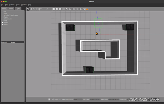
图3-6
启动键盘控制:
$ rosrun ares_description keyboard_teleop.py
运行cartographer的建图功能,Operate the keyboard to start drawing,如图3-7、3-8、3-9所示:
$ roslaunch cartographer_ros demo_revo_lds.launch
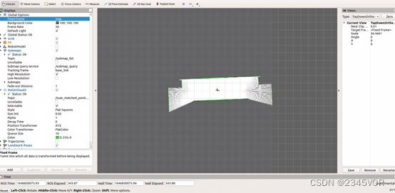
图3-7
图3-8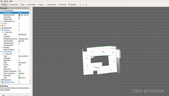
图3-9
建图完成后,运行下列程序,Execute the function to save the map,Provide the required map for subsequent navigation,如图3-10所示:
$ rosrun map_server map_saver -f ~/map
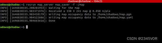
图3-10
2) SLAM导航
After the above construction is completed,Let's test the navigation capabilities of the Ackerman model,Considering the ackerman similar model and the real car,base_local_planner 和dwa_local_plannerDon't adapt to the ackerman,Therefore, in the process of building the map, we choosetebalgorithm to simulate,Open the simulation environmentgazebo可视化界面,如图3-11,Load radar and associated sensor data:
$ roslaunch bringup ares_gazebo_rviz.launch
图3-11
First we look at the navigation functionmove_base.launch文件的相关配置:
<launch>

   <node pkg="move_base" type="move_base" respawn="false" name="move_base" output="screen">
    <rosparam file="$(find bringup)/param/costmap_common_params.yaml" command="load" ns="global_costmap" />
    <rosparam file="$(find bringup)/param/costmap_common_params.yaml" command="load" ns="local_costmap" />
    <rosparam file="$(find bringup)/param/local_costmap_params.yaml" command="load" />
    <rosparam file="$(find bringup)/param/global_costmap_params.yaml" command="load" />
    <rosparam file="$(find bringup)/param/teb_local_planner_params.yaml" command="load" />
    <rosparam file="$(find bringup)/param/move_base_params.yaml" command="load" />

    <param name="base_local_planner" value="teb_local_planner/TebLocalPlannerROS" />
    <!--<param name="controller_frequency" value="10" /> <param name="controller_patiente" value="15.0"/>-->
   </node>


   	<node name="map_server" pkg="map_server" type="map_server" args="$(find bringup)/map/map.yaml" output="screen">
                <param name="frame_id" value="map"/>
    </node>

    <!--<node pkg="tf" type="static_transform_publisher" name="odom_to_map" args="0 0 0 0 0 0 1 /odom /map 100" />-->

    <!--<include file="$(find bringup)/launch/robot_amcl.launch.xml" />-->

   <node name="nav_sim" pkg="ares_description" type="nav_sim.py" >
    </node>

   <arg name="use_map_topic" default="True"/>
    <arg name="scan_topic" default="/scan"/>
    <arg name="initial_pose_x" default="-0.5"/>
    <arg name="initial_pose_y" default="0.0"/>
    <arg name="initial_pose_a" default="0.0"/>
    <arg name="odom_frame_id" default="odom"/>
    <arg name="base_frame_id" default="base_footprint"/>
    <arg name="global_frame_id" default="map"/>
  <node pkg="amcl" type="amcl" name="amcl">
      <param name="use_map_topic" value="$(arg use_map_topic)"/>
      <!-- Publish scans from best pose at a max of 10 Hz -->
      <param name="odom_model_type" value="diff"/>
      <param name="odom_alpha5" value="0.1"/>
      <param name="gui_publish_rate" value="10.0"/>
      <param name="laser_max_beams" value="810"/>
      <param name="laser_max_range" value="-1"/>
      <param name="min_particles" value="500"/>
      <param name="max_particles" value="5000"/>
      <param name="kld_err" value="0.05"/>
      <param name="kld_z" value="0.99"/>
      <param name="odom_alpha1" value="0.2"/>
      <param name="odom_alpha2" value="0.2"/>
      <!-- translation std dev, m -->
      <param name="odom_alpha3" value="0.2"/>
      <param name="odom_alpha4" value="0.2"/>
      <param name="laser_z_hit" value="0.5"/>
      <param name="laser_z_short" value="0.05"/>
      <param name="laser_z_max" value="0.05"/>
      <param name="laser_z_rand" value="0.5"/>
      <param name="laser_sigma_hit" value="0.2"/>
      <param name="laser_lambda_short" value="0.1"/>
      <param name="laser_model_type" value="likelihood_field"/>
      <!-- <param name="laser_model_type" value="beam"/> -->
      <param name="laser_likelihood_max_dist" value="2.0"/>
      <param name="update_min_d" value="0.1"/>
      <param name="update_min_a" value="0.2"/>
      <param name="odom_frame_id" value="$(arg odom_frame_id)"/>
      <param name="base_frame_id" value="$(arg base_frame_id)"/>
      <param name="global_frame_id" value="$(arg global_frame_id)"/>
      <param name="resample_interval" value="1"/>
      <!-- Increase tolerance because the computer can get quite busy -->
      <param name="transform_tolerance" value="1.0"/>
      <param name="recovery_alpha_slow" value="0.0"/>
      <param name="recovery_alpha_fast" value="0.0"/>
      <param name="initial_pose_x" value="$(arg initial_pose_x)"/>
      <param name="initial_pose_y" value="$(arg initial_pose_y)"/>
      <param name="initial_pose_a" value="$(arg initial_pose_a)"/>
      <remap from="/scan" to="$(arg scan_topic)"/>
      <remap from="/tf_static" to="/tf_static"/>
    </node>

   </launch>
This section loads the relevant configuration parameters of the global and local planning necessary for navigation and the relevant configuration parameters of the cost map,And given noGPSPosition the car,选用amclMore precise positioning of Ackermann trolleys.
重启一个终端,运行下列命令,如图3-12: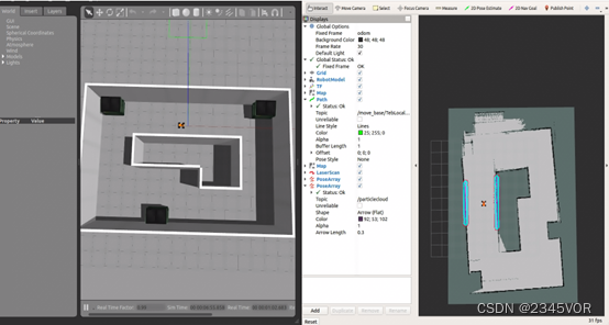
$ roslaunch bringup move_base.launch
图3-12
使用rviz中的2D Nav Goalpublish target,AresAckermann car will automatically navigate to this point,效果如下图3-13、3-14、3-15所示: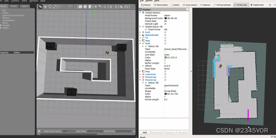
图3-13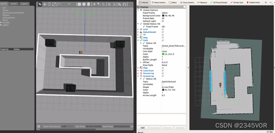
图3-14
图3-15
四、 总结与展望
至此,cartographerThe reproduction of the official function package and the mapping verification of your own Ackerman model,It can be proved that the mapping effect of the mapping algorithm is better thangmapping等传统的2D建图效果,主要体现在cartographerThe loopback detection function of,We can find that in the course of construction drawing,The algorithm can continuously adjust and optimize the map created at the same time,It's traditionalslamFeatures that algorithms don't have;In the following time, we will consider the integration of the Ackerman vehicles.rgbd相机,实现相机+lidar fusionrtabmap slam算法,并不断优化cartographerRelated parameters of the function package and related configuration of Ackerman.在导航方面,will be added to the optimizedA*Algorithms to perform related navigation functions.And control the Ackerman smart car to realize the function of object target recognition and lane line detection and line patrol in the navigation process,And realize real-time communication with the host computer.
边栏推荐
- 突破次元壁垒,让身边的玩偶手办在屏幕上动起来!
- 服务器和客户端的简单交互
- 【每日一题】640. 求解方程
- Primavera Unifier - AEM Form Designer Essentials
- 使用stream实现两个list集合的合并(对象属性的合并)
- PowerMock for Systematic Explanation of Unit Testing
- Convolutional Neural Network System,Convolutional Neural Network Graduation Thesis
- canvas图形操作(缩放、旋转、位移)
- ES6:数值的扩展
- Primavera Unifier advanced formula usage sharing
猜你喜欢
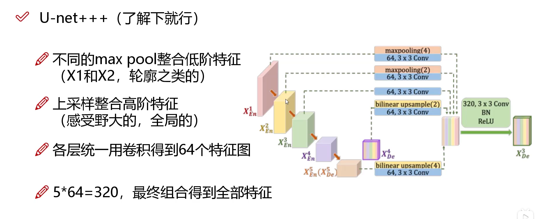
Network model (U - net, U - net++, U - net++ +)
Six functions of enterprise exhibition hall production
Network Models (DeepLab, DeepLabv3)
代码签名证书可以解决软件被杀毒软件报毒提醒吗?
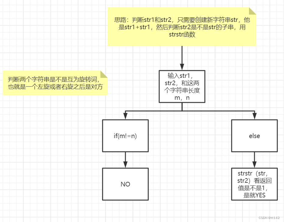
【剑指offer】左旋字符串,替换空格,还有类题!!!
MongoDB 非关系型数据库
How to improve the efficiency of telecommuting during the current epidemic, sharing telecommuting tools
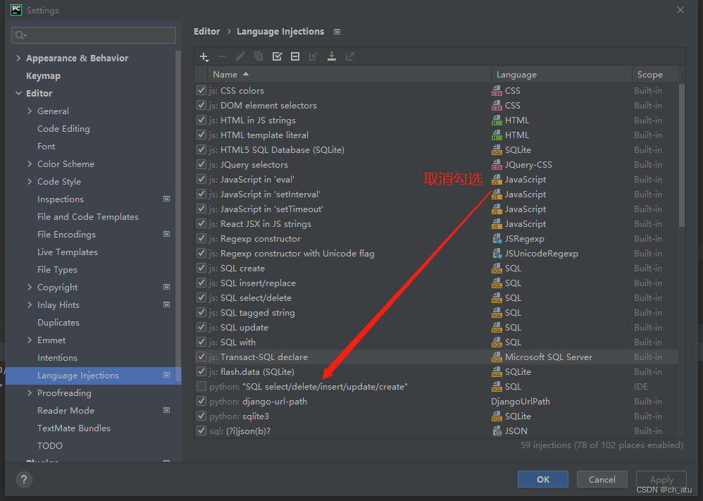
pycharm cancel msyql expression highlighting
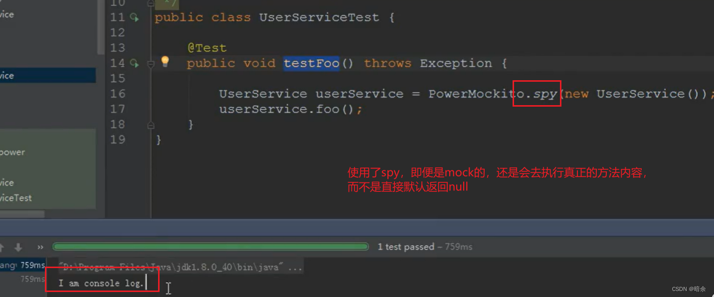
单元测试系统化讲解之PowerMock
HDRP Custom Pass Shader Get world coordinates and near clipping plane coordinates
随机推荐
NT 内核函数原型大全
软件定制开发——企业定制开发app软件的优势
How to improve the efficiency of telecommuting during the current epidemic, sharing telecommuting tools
爆料!前华为微服务专家纯手打500页落地架构实战笔记,已开源
网络流行简笔画图片大全,关于网络的简笔画图片
Have you encountered this kind of error? flink-sql writes to clickhouse
Primavera P6 Professional 21.12 登录异常案例分享
What is the difference between the qspi interface and the ordinary four-wire SPI interface?
&gt; 家乡旅游景点网页作业制作 网页代码运用了DIV盒子的使用方法,如盒子的嵌套、浮动、margin、border、backgro
突破次元壁垒,让身边的玩偶手办在屏幕上动起来!
数字钱包红海角逐,小程序生态快速引入可助力占领智慧设备入口
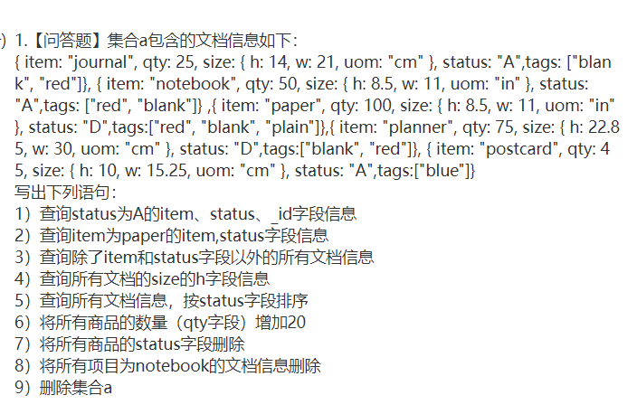
SQL statement
TIOBE - 2022年8月编程语言排行
网络模型(U-net,U-net++, U-net+++)
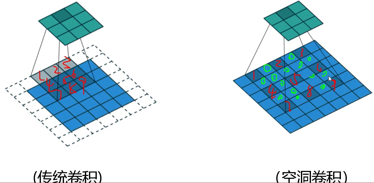
自定义卷积核的分组转置卷积如何实现?
Typora and basic Markdown syntax
Network model (U - net, U - net++, U - net++ +)
go基础之并发
Data middle platform program analysis and development direction
opencv 制作趣图