当前位置:网站首页>UML learning reprint
UML learning reprint
2022-04-23 22:05:00 【Scarcity risk humility】
Chapter one Overview of object-oriented technology
Software crisis and software engineering
The basic method of controlling the complexity of software system :
(1) decompose
For complex software systems , It can be gradually broken down into smaller and smaller components , Until it can no longer be decomposed . Such as Unix Medium shell And pipeline adopt the decomposition idea .
(2) abstract
When we use the concept of abstraction , We acknowledge that the issue under consideration is complex , But we are not going to understand the whole problem , And just choose to solve the main part , Don't pay attention to those details .
Abstraction is divided into process abstraction and data abstraction ( data type )
Before the rise of object orientation , Programming is process centric , For example, structured design method . However , The system has reached the extreme of complexity beyond its processing capacity . With the object , We can raise the level of abstraction to build larger , More complex systems .
(3) modularization
High cohesion , Low coupling . High cohesion means that logically related computing resources should be gathered as much as possible in a module ; Low coupling means that the interaction between modules is as little as possible
(4) Information concealment
Information concealment is also called encapsulation , Isolate the implementation details in the module from the outside world , Users only need to know the function of the module , Without knowing the internal details of the module .
In a structured approach , The real world is mapped to a collection of functions . In an object-oriented method , Entities and their relationships in reality are mapped to objects and objects
The relationship between .
Objects and examples
object (object) An entity used to describe objective things in a system , It is the basic unit of the system . An object consists of a set of properties and a set of methods that manipulate the properties .
Objects communicate through messages , One object sends a message to another object to activate a function .
example (instance) The concept of is similar to the object , Examples have a broader meaning , Not only for classes , Other modeling elements also have examples . An instance of an object is a class , The instance of association is the chain
class
A class is a collection of objects with the same properties and methods ,( such as : Instance class ) It provides a unified abstract description for all objects belonging to this class . Objects of the same class have the same properties and methods , This means that they are defined in the same form , Instead of saying that the properties of each object are the same .
Class is static , The semantics of classes and the relationship between classes have been defined before the program is executed , And objects are dynamic , Objects are created or deleted during program execution .
encapsulation
encapsulation (encapsulation) Is to combine the attributes and methods of an object into an independent unit , And hide the internal details of the object as much as possible
Encapsulation makes the object two parts : Interface and implementation part , For users , The interface is visible , The implemented part is invisible .
Encapsulation provides two types of protection . 1 It can protect objects , Prevent users from directly accessing the internal details of the object .
2 It can protect the client , In case of side effects caused by changes in the implementation part of the object , That is, the change of the implementation part will not affect the corresponding customers
End change
Inherit
Inheritance is that a subclass can inherit the properties or methods of its parent class .
Inheritance benefits : 1 Increased opportunities for software reuse , It can reduce the cost of software development and maintenance . 2. It can ensure the consistency of classes , The parent class can customize rules for all subclasses , Subclasses must follow these rules .
Such as :c++ The virtual function , java And so on .
polymorphic
In object-oriented technology , Polymorphism refers to the ability of an entity to have different meanings or usages in different contexts
Polymorphism is often associated with coverage , Binding and other concepts . Polymorphism is one of the important means to ensure that the system has good adaptability .
news
news (message) Is the object-oriented service request . It contains the identity of the object providing the service , Method identification , Input information and answer information, etc .
news : Including synchronous messages and asynchronous messages . If the message is asynchronous , Then an object continues its activity after sending a message , Don't wait for the message recipient to return the result . And functions are often synchronized , The function caller waits for the receiver to return the result .
Chapter two UML summary
UML The composition of the
- Basic building blocks :
Relationship ( rely on dependency, relation association, generalization generalization, Realization realization)
chart (diagram)
thing (thing):
(1). Structural things (structural thing): class (class), Interface (interface), Collaboration (collaboration), Use cases (use case), Active class (action
class), artifacts (component) And nodes (node)
(2). Act things (behavioral thing): Interaction (interaction) and State machine (state machine)
(3). Group things (grouping thing): package (package)
(4). Annotate things (annotational thing): uml The annotations in
- The rules (rule)
- Public mechanism (common mechanism)
- Five semantic rules
name , Range , visibility , integrity , perform
5. General mechanism :
1 Specification specification ,
2. modification
3. General division ,
4. Extension mechanism , The extension mechanism includes version , Marker value , constraint
UML The view of
UMl View in :
Use case view : Indicates the functional requirements of the system
Logical view : Represent the conceptual design and subsystem structure of the system
Implementation view : Explain the structure of the code
Process view : Explain the concurrent execution and synchronization in the system
Deployment diagram : Used to define the physical structure of the hardware node
UMl Application fields of
software development , Finance … It 's a huge range
UML Application example of
The third chapter Use case diagram : The beginning of modeling
What is modeling
Choose an angle , Abstract reality . such as , American coffee and latte , Abstract the two , You get their parent class : Coffee
In the process of unification , A use case is an analysis unit , Design unit , Development unit , Test unit , Even deployment units .
Basic concept of use case diagram
Use case diagram and collaboration diagram , Sequence diagram , Together, activity diagrams form the use case view
Use case diagrams are the first step in requirements analysis , Use case diagrams are used to describe the set of functional requirements of the system
stay uml in , Use case diagrams are represented by ellipses .
The concept of participants
Participants are those outside the system , Things that need to use or interact with the system , Including people , equipment , External systems, etc .
for example :
1. Possible participants in the banking system : Customer Management manufacturer Mail System
2. Possible participants in the educational administration system : Student Teachers' Administrators
Case study : I want to send you a letter , Gave the letter to the post office staff . At this time , You are a participant , Staff are not participants , But business workers .
Find and identify participants
Modeling starts by looking for an abstract perspective , that , Defining participants is the beginning of our search for abstraction , Participants are at the core of modeling
To find the participants , We need to ask two questions :
1. Who has clear objectives and requirements for the system and takes the initiative to take action ?
2. Who does the system serve ?
for example : Xiao Wang goes to the bank to open an account , Asked the hall manager about the handling process , Fill out the form and give it to the counter clerk , Finally get the bank passbook .
In this case , Xiao Wang is a participant , The lobby manager and counter staff are business workers .
checkpoint
There are two questions to ask :
Find all participants ?
Whether each participant involves at least one use case ?
for example , In a beverage vending machine , There are three participants
The relationship between the participants
Because participants are actually classes , therefore , There are also inheritance relationships between participants ( generalization ).
The generalized relationship between participants represents the relationship between parent participants and child participants . Child participants can not only inherit the behavior and meaning of the parent participant , You can also add your own unique behavior and meaning .
The generalization relation is represented by a solid with a triangular arrow .
for example :
Use cases
Definition : Use cases are systems , Subsystem or class and Description of the action sequence of external participant interaction , Including optional action sequences and action sequences with exceptions
stay uml in , The use case is represented by an ellipse , Use cases are often named with verb object structure or subject predicate structure
Using use cases for requirements analysis has the following characteristics :
1. Use cases describe the information in the system from the perspective of using the system
2. The use case describes some visible requirements proposed by the user
3. Use cases are dynamic descriptions of system behavior
Use cases are conditional , Such as cooking :
To cook , First, there must be rice , This is the premise of starting the use case , Also known as preconditions ; After the use case is executed , We'll get a result : Rice becomes rice , This is called a post condition .
The complete use case is defined by the actor , precondition , scene , The post condition constitutes .
3.6 Use case analysis
The basis for judging whether the use case is accurate :
1. Use cases are relatively independent . ( This means that the purpose of the participants can be accomplished alone without other use case interactions . If withdrawing money is a use case , And filling out a withdrawal form is not )
2. The execution results of use cases are observable and meaningful to participants . ( For example, the login system is an effective use case , But entering the password is not )
3. Use cases must be initiated by an actor ( There are no use cases without actors , Nor should a use case start itself and actively start another use case , If you follow ATM Withdrawal is a use case ,
and ATM Spitting money is not )
4. Use cases usually appear in the form of verb object phrases .( Like drinking water and " drink " And water are not )
5. A use case is a requirement unit , Analysis unit , Design unit , Development unit , Test unit , Even deployment units , Once the use case is determined , Other aspects of software development
Activities are based on this use case , Around it .
Granularity of use cases
In the use case analysis phase ,( Conceptual modeling stage ), Use cases should be able to describe a complete business process . If you withdraw money , Borrow books, etc , But don't go down to verifying passwords , Find a single step in the book .
In the system analysis phase , The perspective of use cases is for computers , Granularity is suitable for a use case to describe a complete interaction between the operator and the computer . Such as ( Fill out the application form , Review application form …). Another granularity to refer to is that the development workload of a use case should be about a week .
In the business use case phase , The most standard method is , Based on whether the use case has completed a complete purpose of the participant . ( If borrowing a book is a use case , And look up the bibliography , Querying records and so on is only the process of accomplishing this purpose )
principle : At the same demand stage , The granularity of all use cases should be the same order of magnitude .
Acquisition of use cases
The following questions need to be clear
1. Participants are outside the boundaries of the system
2. Participants have clear expectations and return requirements for the system
3. The expectations and rewards of participants are within the boundaries of the system
Drawing and naming each effective expectation with the help of use cases completes the work of use case acquisition
Misunderstanding of goals and steps
In the use of , Another misconception about use cases is : Confuse goals with steps to achieve them .
A use case is a participant's wish for the target system , A complete event . There are many steps to complete this event , But these steps cannot be completely
Reflect participants' goals , Cannot be used as a use case
Such as sending letters and paying , The granularity of the two use cases is different , The boundaries are different , Obviously, they should not appear in one view at the same time .
Misunderstanding of use case granularity
The first reason for the use case granularity error is : Unclear goals and steps
Such as system management, website management and order modification , obviously , Obviously, the granularity of managing websites is larger than that of modifying orders .
At the same demand stage , The granularity of all use cases must be kept at the same level
Business use cases
Business use case is one of the use case versions , Business modeling dedicated to the requirements phase
From the perspective of business participants, you will see the business boundary rather than the system boundary
Business use case implementation
Business use case implementation , Also known as business use case instance , It is one of the use case versions , Business modeling dedicated to the requirements phase .
Business use case realization is an implementation of business use cases , Like interfaces and implementation classes
The significance of business use case implementation is that it expresses different implementation methods of the same business
For example, there are three ways to pay the phone bill : Payment in the business hall , Bank payment , Save the phone bill in advance
System use cases
System use cases are used to define the scope of the system , Get what you need for functionality . If not emphasized , Readers can equate use cases with system use cases
Use case implementation
The complete name of use case realization is the realization of system use case , A use case implementation represents an implementation of a use case
3.7 The relationship between use cases
Use cases are related to each other except for participants , There is also a certain relationship between use cases , Such as generalization relation , Inclusion relation , Extended relationships, etc .
It can also be used. UML The relationship between user-defined use cases
Generalization relation (generalization)
In programming languages , And " Inherit " The concept is similar
In a generalized relationship , The child use case inherits the behavior and meaning of the parent use case , Child use cases can also add new behaviors and meanings or override the behaviors and meanings of parent use cases
Inclusion relation (include)
Inclusion relation refers to the relation between two use cases , One of the use cases ( Called basic use cases ) The behavior of contains another use case ( It's called including use cases ) act
Containment relationships are versions of dependencies
Extended relationship (extend)
The basic meaning of extension relation base is similar to that of inclusion relation , It is also the version of dependency , That is to say, the extension relationship is a special dependency relationship , It usually means that the basic use case will use the extended use case in a specific case
Unlike the inclusion relationship , The arrow of the extended relationship points from the extended use case to the basic use case
Generalization of use cases , contain , Comparison of extended relationships
Inclusion relation : When executing basic use cases , The part that contains the use case must be executed
Extended relationship : When executing basic use cases , The extension use case is executed only when the requirements of the extension point are met
relation (association): The relationship between actors and use cases
generalization (generalization): Relationships between actors or between use cases
contain (include): The relationship between use cases
Expand (extend): The relationship between use cases
An association is a relationship between two or more class elements . The class element mentioned here is a modeling element , Common class elements include class , participants , Components , data type , Interface , node , The signal , Subsystem , Use cases, etc , Among them, class is the most common class element
The generalization relation is the relation between two class elements
A dependency is a relationship between two elements or sets of elements
Both containment and extension relationships are dependencies
3.8 Use case diagram
A use case diagram is a set of use cases , A diagram of participants and their relationships
Such as the use case diagram of financial and trade system
3.9 Description of use cases
in fact , The use case description is the main part of the use case
The description of use cases should generally include the following contents :
The goal of the use case
How the use case starts
How messages are delivered between actors and use cases
Use cases in addition to the main path , What are the other paths
The system state after the end of the use case
Other contents to be described
All in all , The principle of describing use cases is to write as fully as possible
Use case template ( A little )
Mistakes that beginners make when describing use cases :
Only describe the behavior of the system , There is no description of the participant's behavior
Only describe the behavior of the participants , There is no description of the behavior of the system
The description is lengthy
When describing use cases , You can use a more concise description , Such as merging data items , Provide abstract high-level description
Correct use case description
Use Case: To buy things
Customers use ID And password to enter the system
The system verifies the identity of the customer
Customers provide personal information ( full name , Address , Telephone ), And choose the goods and quantity to buy
The system verifies whether the customer is a regular customer
The system uses the inventory system to verify whether the quantity of goods to be purchased is less than the inventory
…( Omit )
3.10 Ways to find use cases
The steps of use case analysis :
Find out the participants outside the system and the external system , Determine the boundary and scope of the system
Determine the desired behavior of each participant
Name these system behaviors use cases
Use contains , generalization , Extended relationships deal with common or changed parts of system behavior
Script each use case
Drawing use case diagrams
Distinguish between main event flow and abnormal event flow , If necessary , The flow of exceptional events can be treated as a separate use case
Refine the use case diagram , Solve the problem of repetition and conflict between use cases
3.11 Modeling examples
Our school plans to develop an online course selection system , Requirements are as follows :
The administrator enters the system through the authentication of the system management interface , Establish various courses to be offered this semester , Save the course information in the database and modify and delete the system . Students enter the course selection interface through the client according to the student number and password , Here, students can do two operations : Query selected courses , Course selection . Again , Through the business layer , These operations will be stored in the database . The database is deployed on the server , Through an open sql Interface operation database
Identify participants : Administrators , Student , Database agent
Identify use cases :
Student : The user login Query selected courses Course selection pay
Administrators : The user login Add courses Revise the course Delete course
Database agent : All use cases related to database operation
Add course Use case description of :
Chapter four State diagrams and activity diagrams
4.1 What is a state diagram
State diagram (statechart diagram) It is mainly used to describe the dynamic behavior of an object during its lifetime , Represents the sequence of States experienced by an object , The event that causes a state transition (event), And the actions accompanying the state transition (action)
Generally, a state machine can be used for an object ( The object here can be an instance of a class , An instance of a use case or an instance of an entire system ) Life cycle modeling
A state diagram is a diagram used to display a state machine , The focus is on describing the control flow between States
In the state machine , Actions can be related to both States and transitions . If the action is state dependent , When the object enters a state, it will trigger an action , No matter which state you enter this state from . If the action is related to transfer , When the object transitions in different states , The corresponding action will be triggered
Moore machine : All actions are related to state ; Mealy machine : All movements are related to transfer .
4.2 The basic concept of state diagram
state
state (state) A condition or condition in the life cycle of an object , In the meantime, the object will satisfy certain conditions , Perform certain activities or wait for certain events .
All objects have States , A state is the result of an object performing one or more activities , When something happens , The state of the object will change
States can be subdivided into different types , Like the initial state , Terminal state , In the middle , Combined state , Historical status, etc . A state diagram has only one initial state , But the final state can have one or more , Or there can be no end state
The intermediate state consists of two areas : Name field and internal transfer field
Combine States and sub States
A state nested in another state is called a substate (substate), States with sub states are called composite states (composite state).
Pictured W It's a combined state , E and F It's a substate
Sub states can be divided into or Relationship and and Relationship
or Relationship : A sub state can be reached at a certain time
and Relationship : In the combined state, multiple sub states can be reached at the same time at a certain time
The state of history
The state of history (history state) Is a pseudo state , The purpose is to remember the child when exiting from the combined state . When you enter the combined state twice , You can directly enter this sub state , Instead of starting from the initial state of the combination again
The historical state is symbolized by
( Shallow historical state shallow) and
( Deep historical state deep)
The shallow history state means that only the history of the outermost combination state is remembered ; The deep historical state means that the history of the combined state of any depth can be remembered
Transfer (transition)
A transition is between two states A relationship of , Indicates that the object will perform certain actions in the first state , And enter the second state when a specific event occurs and a specific warning condition is met
Generally speaking , Transitions between states are triggered by events , Therefore, the expression that triggers the event should be marked on the transfer . If the event is not indicated on the transfer , It means that the transfer will be triggered automatically after the internal activities in the original state are executed
For a given state , In the end, there can only be one transfer , So from the same state , The conditions between several transitions with the same event should be mutually exclusive .
event (event)
An event is an event that occupies a certain position in time and space , A detailed description of something meaningful .
Call event (call event): Indicates the height of the operation
Change events (change event): If the variable of a Boolean expression changes , Make the value of Boolean expression change accordingly, so as to meet some conditions , This event is called a change event . A change event represents an event to be continuously tested . Keyword for change events when Express
Time event (time event): It refers to the situation that satisfies a certain time expression , For example, at a certain point in time or after a certain period of time . The time keyword is after or when Express
Signal event (signal event): Indicates that the object has received the signal , Signal events often trigger state transitions
" The signal " Is sent asynchronously by one object and received by another object , Named object
For signal version <> Express , There can be generalization between signals , Form a hierarchy
Signal events are similar to call events , A mediator event is an asynchronous event , Call events are generally synchronous events
action
An action is an executable atomic computation , Non interruptible , Its execution time is ignored .
uml Two special actions are specified : Entry and exit actions . The entry action indicates the action performed when entering the state , The exit action indicates the action executed when exiting the state
entry / setMode(onTrack)
exit / setMode(offTrack)
1
2
4.3 What is an activity map
Activity diagram can be used to describe the workflow and concurrent behavior of the system
Activities can actually be seen as a special form of state diagram , After one of the activities is over, go to the next activity immediately ( State transitions in a state diagram may require Events
Trigger )
Activities
An activity represents the execution of a task in a process , It can represent the execution of statements in the process of an algorithm
The distinction between action state and activity state :
The action state is atomic , It can't be broken down , The time taken by their work can be ignored . The purpose of the action state is " Enter the action ", Then turn to another state
The active state is decomposable , It's not atomic , The completion of its work takes some time , The action state can be regarded as a special case of the active state
lane
lane (swimlane) Is the area division in the activity diagram , The system divides all activities according to the responsibilities of each activity , Each lane represents an area of responsibility . Each lane
It's not a one-to-one relationship , The swimlane is concerned with the responsibilities it represents , A swimlane may be implemented by a class , It may also be implemented by multiple classes
Branch
In the activity chart , For the same trigger event , You can turn to different activities according to different trigger conditions , Every possible transfer is a branch (branch)
Two expressions :
Conventional methods
The diamond symbol indicates
Bifurcation and confluence
Bifurcation means that a control flow is replaced by two or more control flows , After bifurcation , These control flows are concurrent
Confluence is the opposite of bifurcation , Represents two or more control flows Merge into one control flow
Such as the example of making a phone call
Object flow
Objects can appear in the activity diagram , Object can be used as the input or output of an activity , The object flow in the activity diagram represents the relationship between activities and objects , Like an activity creating an object
( As the output of the activity ) Or use objects ( As input to the activity )
Object flow belongs to control flow . If there is an object flow between two activities , Then the control flow does not have to draw
4.4 Purpose of activity diagram
Activity diagrams are useful for representing concurrent behavior
The general activity diagram can model the workflow of the system , That is, business modeling of the system
You can model specific operations , Used to describe the relevant details of the calculation process
During use case analysis , Activity diagrams can be used to describe the internal flow of use cases
Developers often use a flowchart to describe an algorithm . stay UML There is no concept of flow chart in , In a sense , The function of the activity diagram has included the process
chart
4.5 Comparison of state diagram and activity diagram
Both state diagram and activity diagram are used to model the dynamic behavior of the system , The two are similar , But there's a difference
First , The focus of the two descriptions is different . A state diagram describes the state of an object and the transition between states , The activity diagram describes the control flow from activity to activity
secondly , They are used in different occasions . If it is to show the behavior of an object in its life cycle , It is better to use the state diagram ; If the goal is to analyze use cases , Understand the workflow involving multiple use cases , Or use multithreaded applications, etc , It is better to use activity diagram
If you want to highlight the interaction between multiple objects , Neither state diagram nor activity diagram is appropriate , Here, it can be represented by sequence diagram or collaboration diagram
4.6 Modeling examples
The fundamental meaning of use case diagram is to clarify the requirements of the system , Lay the foundation for the following system analysis and design .
And use case documents ( Flow of events ) The function of is to describe the internal process of the use case , It is a supplementary description of the use case
The function of activity diagram is similar to that of use case document , But they are two different forms , The audience is also different
The activity diagram is used to describe the... In the course system " Add courses " The event flow of the use case .
course State diagram
The fifth chapter Class diagrams and packages
5.1 The definition of a class
stay UML in , There are two kinds of graphs that are very important , One is the use case diagram , The other is class diagram
The definition of a class : Classes have similar structures , Descriptors of a set of objects with behaviors and relationships
The naming of classes can be divided into two forms , simple name and path name( Such as Util::shape, util It's the name of the bag , Shape yes util A class in )
Attributes of a class
attribute (attribute) Is a property of a named class , It describes the range of values that an instance of this feature can take
Attributes describe some of the characteristics of the event being modeled , These properties are common to all objects of the class
Property visibility :+ - #
+name: int // + The sign means public
-age: int // - The sign means private
#state: boolean // # The sign means protected
1
2
3
Class operation
operation (opeartion) For modification , Retrieve the properties of a class or perform some actions , Operations are often referred to as functions , But they are constrained inside the class , Can only work on this
Class
+display():Location
-hide()
#create()
1
2
3
5.2 Relationships between classes
Generally speaking , The relationship between classes is related , Gather , Combine , generalization , Rely on
relation
relation (association) It is a kind of Marxist connection between model elements , It has common structural characteristics , Behavioral characteristics , The chain of relations and semantics (link) Description of
The concept of chain : The chain is an example , Just as an object is an instance of a class , A chain is an instance of an association , Association represents the relationship between classes , The chain represents the relationship between objects
In the class diagram , Associations are represented by a solid line that connects classes together
An association can have two or more association ends (association end), Each association end is connected to a class
Associations can also have directions
Two way connection
One way Association
// Connections
public class A {
public B b;
}
1
2
3
4
public class B {
String name;
int age
…
}
1
2
3
4
5
(1). Association name
You can add an association name to the association to describe the role of the Association
If the meaning of an association is clear enough , Then there is no need to add relevant joint names
(2). Associated participants
Classes at both ends of the association can participate in the association as some kind of participant
There is also a multiplicity of participants , Indicates how many objects can participate in the association
(3). Association class
Associations have their own characteristics , Through the Association class (association class) You can further describe the associated properties , Operation and other information
The Association class is connected with the association through a dotted line
// Company class
public class Company {
private String companyName;
public Person employee[]; // Employee array
}
1
2
3
4
5
// Person class
public class Person {
private String personName;
protected Company employer; // The boss of the company
//  class "contract" Code for
pubic class Contract {
    private Double salary; //  Salary
}
}
1
2
3
4
5
6
7
8
9
10
Aggregation and combination
Gather (aggregation) Is a special form of Association . Such as classrooms and tables , Not a strong binding relationship , Can be disassembled and exist independently
Combine (composition) It also represents the relationship between the whole and part of the class , But the whole and part have the same life cycle . In other words, combination is a special form of
Gather . for example : The relationship between head and mouth
formula : Aggregate detachable , The combination is not divided
The designer determines whether to use... According to the requirements analysis description aggregation still compostion
generalization
generalization (generalization) Defines the classification relationship between general elements and special elements , From the perspective of object-oriented programming language , Between classes
Generalization relationship is the inheritance relationship between classes
UML The generalization relation is represented by the connecting lines of hollow triangles
rely on
If there are two elements X and Y, If modified X The definition of may lead to another Y Modification of the definition of , said Y Depend on X
For a class , rely on (dependency) May be caused by various reasons , For example, one class sends a message to another class , Or a class is a data member of another class , Or one class is the parameter type of the operation of another class
Sometimes it is difficult to distinguish between dependency and association . in fact , If a class A And the class B There is a correlation between , So class A And the class B There are dependencies . But if
There is an association between the two classes , Just show the relationship , There is no need to indicate that there is a dependency between the two classes .
Different from the relation, the relation is , Dependencies themselves do not generate specialized implementation code
in addition , Similar to generalization , Dependencies are not limited to classes , Other modeling elements also have
5.3 Derived properties and derived associations
Derived properties (derived attribute) Associated with derivation (derived association) It refers to the attributes and associations derived from other attributes and associations
Such as Person Class age Property is a derived property , Because a person's age can be calculated from the current date and his date of birth .
In the class diagram , The name of the derived association needs to be preceded by "/"
When generating code , Derived properties and derived associations do not produce corresponding code .
Indicating that some attributes and associations are derived attributes and derived associations help ensure data consistency
5.4 Abstract classes and interfaces
abstract class (abstract class) Is a class that cannot directly generate instances , Because methods in abstract classes are often just declarations , Without concrete realization , So you can't draw on each other
Class instantiation
UML The class is expressed in italics
Interfaces are classes <> Version
interviewer : Please talk about it java Understanding of abstract classes and interfaces
Interfaces and abstract classes are the upper layer of the inheritance tree , Their common ground is as follows :
They are all the abstraction layers of the upper layer .
Can't be instantiated
Can contain abstract methods , These abstract methods are used to describe the functions of classes , But no specific implementation is provided .
Their differences are as follows :
You can write non abstract methods in abstract classes , So as to avoid writing them repeatedly in subclasses , This can improve the reusability of the code , This is the advantage of abstract classes ; There can only be abstract methods in an interface .
A class can only inherit one direct parent class , This parent class can be either a concrete class or an abstract class ; But a class can implement multiple interfaces .
Java The reason why class inheritance in language is single inheritance is : When a subclass overrides a parent method , Or hide the member variables and static methods of the parent class ,JVM Use different binding rules . If a class has more than one direct parent , Then the binding rules become more complex . In order to simplify the software architecture and binding mechanism ,java Languages prohibit multiple inheritance .
Interfaces can inherit more , Because there are only abstract methods in the interface , There are no static methods and non constant properties , Only the implementation class of the interface will override the methods in the interface . Therefore, if a class has multiple interfaces, it will not increase JVM Binding mechanism and complexity .
For an existing inheritance tree , You can easily Abstract new interfaces from classes , But it's not so easy to abstract new abstract classes from classes , Therefore, the interface is more conducive to the maintenance and reconstruction of software system .
If Sparrow Inheritance class Bird class ,Boyin Inherit Airplane class ,Sparrow and Boyin Want to use the same flay There is no way to realize the method , Because class inheritance is single inheritance .
5.5 Version
Version (stereotype) yes UML Of 3 One of the extension mechanisms , UML The other two extension mechanisms in are tag values (tagged value) And constraints (constraint)
UML Some versions are defined in , For example, the version of the package has subsystems, etc , The version of class has an interface , participants , Boundary class , The control class , Entity, etc. , Of course , Users can also define their own version
5.6 Class diagram
Classes and the relationships between them form a class diagram , Class diagrams can contain interfaces , package , Relationship and other modeling elements , You can also include objects , Chain, etc .
so to speak , Class diagram describes the static relationship between classes .
Unlike the data model , Class diagrams not only show the structure of information , It also describes the behavior of the system
The abstraction level of class diagram
Class diagrams used at different stages of software development have different levels of abstraction , General class diagrams can be divided into 3 A hierarchical
The conceptual level (conceptual) Class diagrams describe concepts in the application domain . When drawing concept layer class diagram , Little or no consideration of implementation issues , therefore , The concept level class diagram is independent of the specific programming language
Description layer (specification) The class diagram describes the interface part of the software , Not the implementation part of the software
Implementation layer (implementation) Class diagrams really consider the implementation of classes , The part that provides the implementation details of the class
Such as circle
The concept level class diagram has only one class name
The description layer class diagram has a class name , Property name and method name , But there is no type description for the attribute , The language close to the real world is often used in the description
The implementation layer class diagram gives a detailed description of the properties and methods of the class , The implementation layer class diagram is probably the most commonly used class diagram for most people .
You can use version <> Explain that a class is the implementation layer , use <> A class is a description layer or a concept layer , Of course , Can also be
Specify in particular by not using the version
Construct class diagram
Determine the candidate of the class according to the nouns in the use case description . such as , Look for nouns or noun phrases from the event stream , Classify those of the same nature , Or classify the negative and positive contents into one category . In the flow of events , Nouns can be divided into 4 Types : participants , class , Class properties and expressions
Use CRC Find classes by analysis . CRC It's a class (class), duty (responsibility) And collaboration (collaboration) For short . CRC The analysis method is based on the role of the class
To determine the class
According to the boundary class , Control the division of classes and entity classes to help find classes in the system . Analyze the field , Or use the existing domain analysis results to get the class
Refer to the design pattern to determine the class . Such as factory mode
Find classes according to the guidance provided by some software development processes
Don't fall into implementation details too early when constructing class diagrams , According to the different stages of project development , Use different levels of class diagrams
If you are in the analysis stage , Concept level class diagram should be drawn ; When starting software design , The class diagram of the illustrative layer should be drawn ; When considering a specific implementation technology , The implementation layer should be drawn
Class diagram
5.7 The basic concept of the package
A bag is like a container , It can be used to organize relevant elements in the model to make it easier to understand
Packages can contain other modeling elements , Such as class , Interface , artifacts , node , Use cases , Bag, etc
The elements in the package can also be visibility controlled
+ Express public - Express private # Express protected
AWT There are three elements in the package :
among window The visibility of is public, Represents any import AWT In the bag of the bag , Can quote window Elements
Form The visibility is protected, Only AWT Only the sub package of the package can reference Form Elements
EvenHandler The visibility of is private, Only in AWT Only in the package can you reference EventHandler Elements
There are two ways to name packages , Simple package name and path package name . Such as Sensors::Vision
The dependency versions in the following figure are <>, Indicates that the source package will access the contents of the destination package , At the same time, the contents of the destination package are added to the namespace of the source package ,
In this way, the content in the destination package does not need to be qualified by package name , Just use the name of the element in the destination package
[ Failed to transfer the external chain picture , The origin station may have anti-theft chain mechanism , It is suggested to save the pictures and upload them directly (img-x855TN2y-1631930294569)(image-20210615165500840.png)]
In data modeling , Use packages to represent patterns and domains , The transformation between data model and object model is carried out in package
stay Web Modeling , A package can represent a virtual directory (virtual directory), All in this directory Web The elements are in this package
5.8 Modeling examples
Take the course as an example , Introduce the use of StarUml establish Course Class process
Chapter six Interaction diagram : Implementation of use cases
6.1 Interaction diagram overview
stay UML in , The implementation of use cases is specified and illustrated by interaction diagrams
The interaction diagram models the dynamic characteristics of the system by displaying the relationship between objects and the messages processed between objects
Interaction diagram includes sequence diagram and collaboration diagram
The sequence diagram describes the message exchange of objects in chronological order , The collaboration diagram focuses on how the system components work together
Sequence diagram and collaboration diagram express the interaction and behavior in the system from different angles , They can be transformed into each other
Interaction diagrams and class diagrams can complement each other , The class diagram fully describes the class , However, the expression of message interaction between objects is not detailed enough , Although the interaction diagram is not tested
Consider all classes and objects in the system , But it can represent the interaction between several objects in the system
6.2 Sequence diagram
Sequence diagram is also called sequence diagram . A sequence diagram is a diagram showing the interaction between objects , These objects are arranged in chronological order .
Sequence diagram composition :
object : Represented as a rectangle , Object names are underlined
news : Use marked arrows to indicate
Lifeline : Indicated by dotted line
Control the focus : Use a very narrow rectangle to represent
The sequence diagram is the time axis in the vertical direction , The horizontal axis represents the class meta participants of each independent object in the collaboration . When an object exists , The lifeline is represented by a vertical dotted line , Be the object
When the process is active , The lifeline is a two-way line
Messages are represented by arrows from the lifeline of an object to the lifeline of an object
It is common practice to place the objects represented on both sides of the diagram , For example, the participant representing the person is placed on the far left , Indicates that the participants of the system are placed on the far right
Named objects in the sequence diagram 3 Ways of planting
The control focus is the symbol representing the time period in the sequence diagram .6.3 Message in sequence diagram
Call message
The sender of the calling message passes control to the receiver of the message , And then stop the activity , Wait for the message recipient to give up or return control . Call messages can be used to indicate synchronization
The meaning of
Asynchronous messaging
The sender of an asynchronous message transmits the signal to the receiver of the message through the message , Then continue your , Do not wait for the receiver to return a message or control
Return message
The return message indicates that... Is returned from the procedure call
If it is returned from a procedure call , The return message is implicit , Therefore, the return message can not be drawn , For non procedure calls , If there is a return message , It must be made clear that
come out
Block messages and timeout messages ( Not commonly used )
Blocking message means that the message sender sends a message to the message receiver , If the recipient cannot receive the message immediately , Then the sender abandons the message
Timeout message refers to the message sender sending a message to the receiver and waiting for a specified time . If the recipient cannot receive the message within the specified time , Then the sender abandons this
news
6.4 Collaboration map
Insert picture description here
Collaboration diagram is a diagram used to describe how the system behavior is realized by the cooperation of various parts , The modeling elements included in the collaboration diagram are objects ( Include participant instances , Multiple objects , Take the initiative
Object etc. ), news , Chain, etc
The collaboration diagram is composed of participants , object , Basic elements such as connections and messages
object
Represents the object participating in the collaboration
In the collaboration diagram , Multi object refers to a collection of objects composed of multiple objects , Generally, these objects belong to the same class
When you need to send messages to multiple objects at the same time instead of objects , We need to use the concept of multiple objects .
The multiple objects of the collaboration diagram are represented by the overlap of multiple boxes , The multi object display of sequence diagram is the same as that of single object
Object association
Object association connects two objects , Indicates the relationship between the two , Also known as chain
news
The message definition of collaboration diagram is exactly the same as that of sequence diagram
Message number
The message sequence number is part of the message , The sequence number indicates the order of message delivery
6.5 Comparison of sequence diagram and collaboration diagram
The sequence diagram emphasizes the time sequence of messages , The collaboration diagram emphasizes the organization of the objects involved in the interaction
Sequence diagrams are used to represent algorithms , The life of the object , Objects with multithreading characteristics have more advantages , Collaboration graph has more advantages in representing concurrency control
The connection between objects cannot be represented in the sequence diagram ( namely " chain "), Multiple objects and active objects cannot be displayed directly , Collaboration diagrams can represent
A collaboration diagram cannot represent the bifurcation of a lifeline (fork), And the sequence diagram can show
6.6 Problem analysis
Interested readers can refer to books page127, No more details here
6.7 Modeling examples
Sequence diagram ( Use cases : Users buy tickets )
Chapter vii. Data modeling
7.1 Overview of data modeling
E-R Figure refers to the entity , Relationship , attribute 3 A basic concept is the basic structure of breakup data , So as to describe the conceptual pattern of static data structure .
E-R The problem is that we can only focus on data , Instead of modeling behavior , Like triggers (trigger), stored procedure (stored procedure) And so on
UML More descriptive , UML The class diagram of can be regarded as E-R Extension of graph .
Class diagrams can be used to describe data as patterns (database schema), And database tables , Use class operations to describe triggers and stored procedures
7.2 The basic process of database design
Database design mainly involves three stages , Conceptual design , Logical design and physical design
The conceptual design stage is to unify the user's information requirements into an overall logical structure , This structure can express the requirements of users , And independent of any database management system
system (DBMS) Software and hardware
The task of the logical structure design stage is to convert the results obtained in the conceptual design stage into those used first DBMS Logical structure consistent with the supported data model
Any in the physical design stage is to select a physical structure that best meets the application requirements for a given data structure model . The physical structure of the database includes the storage record format of the database , Storage record arrangement , Access method, etc .
Concepts in databases Version Applied UML Elements
Version commonly used in database modeling
7.3 Database design steps
Interested readers can check books Page141, No more details here
7.4 Transformation between object model and data model
Interested readers can check books Page141, No more details here
Chapter viii. Component drawing and two-way engineering
8.1 What is a component diagram
Components are the physical components that the system follows a set of interfaces and provides its implementation , Replaceable parts .
The component diagram shows the primary components and the relationship between them , Including the compilation , Dependencies between components when linking or executing
The figure is an example of a component diagram , Express .html file .exe Document and .dll Document the interdependencies between these components
A component is an actual file , It can be of the following types :
Component deployment (deployment component), Such as .dll file , .exe Documents, etc.
Work product components (work product component), Such as source code file , Data files , These artifacts can be used to generate deployment artifacts
Execution components (execution component), That is, the components obtained after the system execution
8.2 The function of component diagram
Component diagram can model the following aspects :
Modeling the relationship between source code files
Modeling the relationship between executable files
8.3 Tool support of component diagram
Forward engineering
Forward engineering is to generate source code according to the model , Of course, after getting the source code, you can call the corresponding compiler to get the executable code
Get the model through code
The specific details will not be repeated here , Interested readers can consult books P158 that will do .
Chapter nine Deployment diagram
9.1 What is a deployment diagram
Deployment diagram is also called configuration diagram or implementation diagram , It's right OO One of the two diagrams for modeling the physical aspects of the system ( Another diagram is the component diagram )
The deployment diagram can be used to display the topology and communication path of the computing nodes in the system and the software components running on the nodes
A system model can get a deployment diagram , Deployment diagrams are often used to understand distributed systems
9.2 Basic concepts in deployment diagram
The deployment map has two ingenious concepts : Nodes and connections
node
Nodes exist at runtime , Represents the physical element of the computing resource , Nodes generally have some memory , And learning often has the ability to deal with
A node can represent a physical device and the software system running the device , Such as UNIX host , Sensors, etc .
The connection between nodes indicates the communication path between systems , This communication path is called connection (connection)
There are two types of nodes in the deployment diagram , The processor (Processor) And equipment (Modem)
A processor is a hardware component that can execute programs , In the deployment diagram , It can explain which processes are in the processor , Process priority and process scheduling mode, etc
The device is a hardware structure without computing power , Such as modem , Terminals, etc .
9.3 An example of a deployment diagram
Microservice deployment diagram ( Shopping websites )
pc, peripherals , And ISP Connection deployment diagram
9.4 Modeling examples
Chapter ten Modeling case analysis
10.1 introduction
Interested readers can check books Page174, Only one class diagram is provided here
————————————————
Copyright notice : This paper is about CSDN Blogger 「 I fought with you 」 The original article of , follow CC 4.0 BY-SA Copyright agreement , For reprint, please attach the original source link and this statement .
Link to the original text :https://blog.csdn.net/zhuiQingran/article/details/120361736
版权声明
本文为[Scarcity risk humility]所创,转载请带上原文链接,感谢
https://yzsam.com/2022/113/202204232201249988.html
边栏推荐
- [leetcode sword finger offer 28. Symmetric binary tree (simple)]
- 五个拿来就能用的炫酷登录页面
- Beijialai touch screen maintenance 4pp065 0571-X74F
- [leetcode refers to offer 47. Maximum value of gift (medium)]
- Oracle intercepts special characters
- OpenFeign超时设置
- NVM introduction, NVM download, installation and use (node version management)
- Ali has another "against the sky" container framework! This kubernetes advanced manual is too complete
- Pycharm Chinese plug-in
- Database experiment VI integrity language experiment
猜你喜欢

三、zygote启动流程
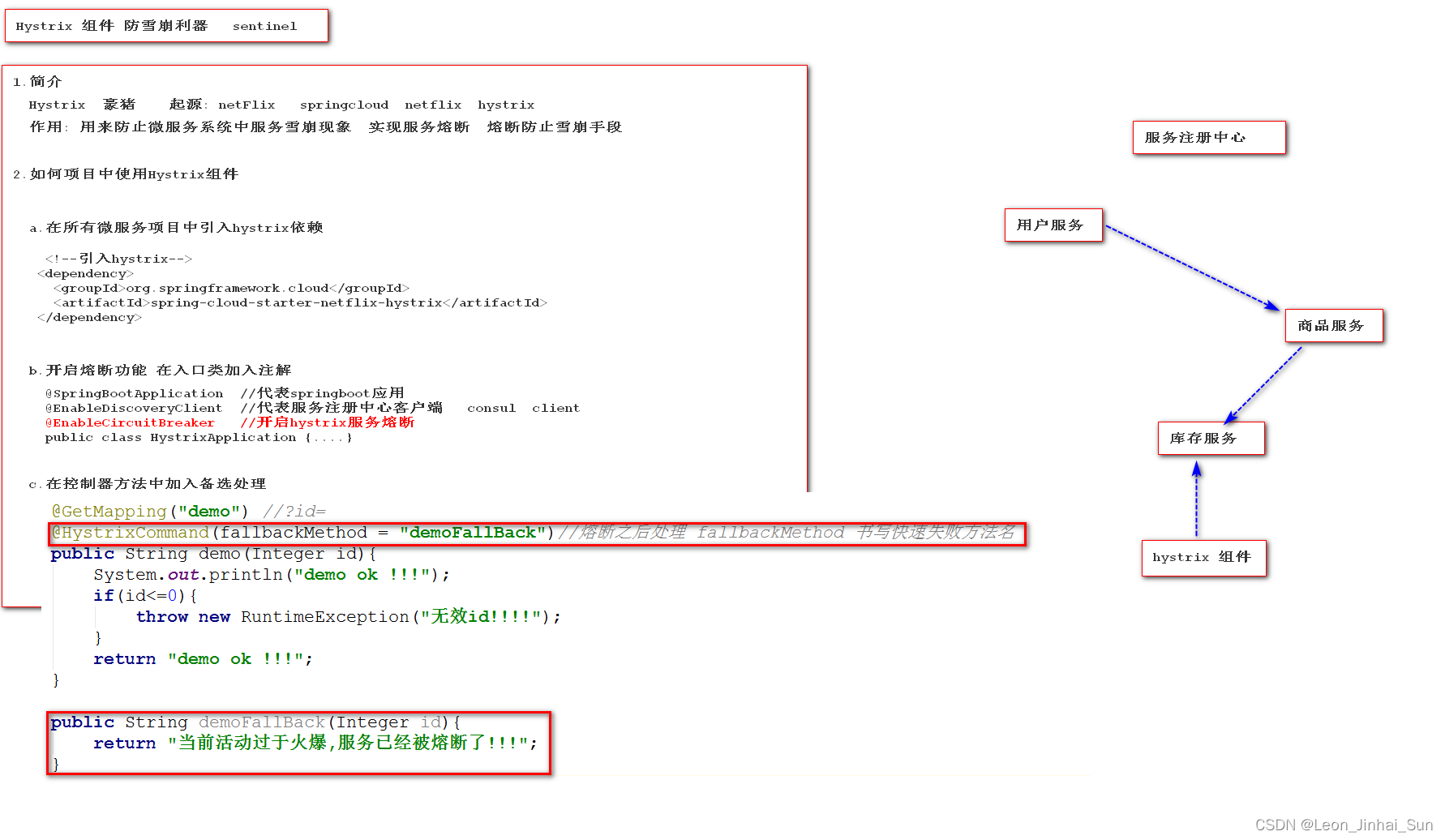
Hystrix简介和服务端熔断的实现
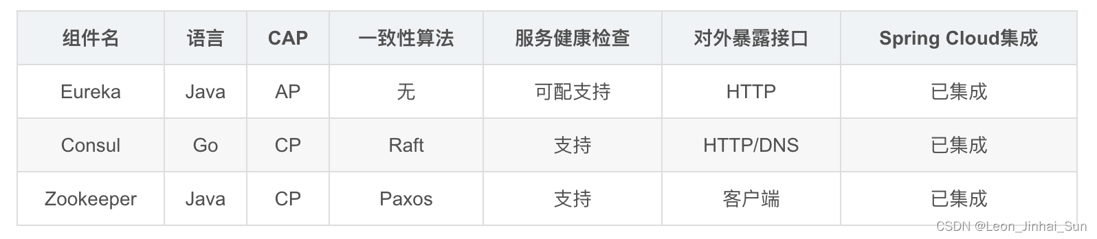
不同注册中心区别
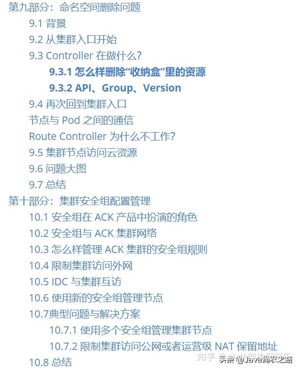
Ali has another "against the sky" container framework! This kubernetes advanced manual is too complete
A method of asynchronous response of application service through load balancing
Siemens CNC machine tool maintenance panel 1af5200a2-840a
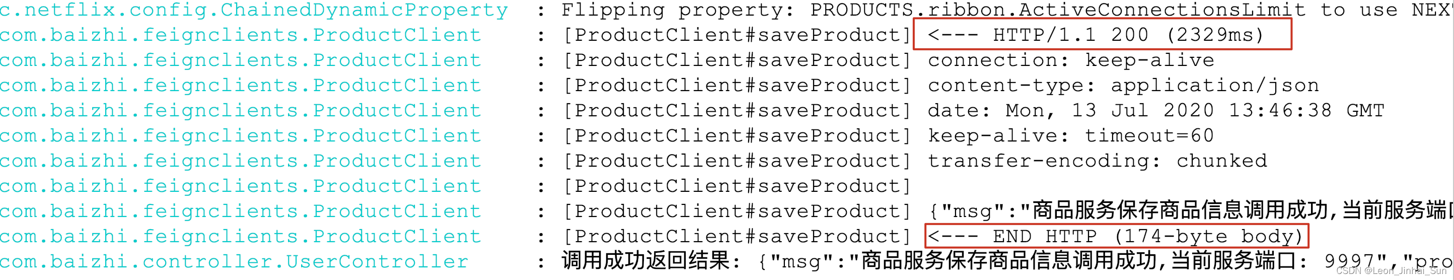
OpenFeign调用详细日志展示
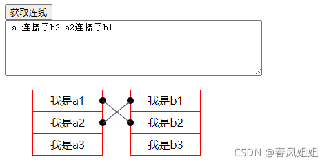
Based on jsplumb JS to achieve multi list one to many connection effect
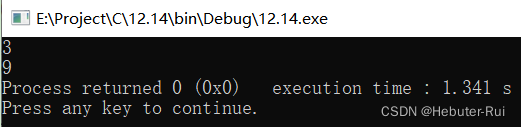
C language programming based on loop structure (PTA)
![[leetcode refers to offer 22. The penultimate node in the linked list (simple)]](/img/f1/4d5a3552d1c09d2dfa81e0cfc1547e.png)
[leetcode refers to offer 22. The penultimate node in the linked list (simple)]
随机推荐
Pytorch installation link sharing
不同注册中心区别
OpenFeign 组件说明
Database Experiment 7 stored procedure experiment
Beijialai touch screen maintenance 4pp065 0571-X74F
April 24, 2022 Daily: current progress and open challenges of applying deep learning in the field of Bioscience
Pytorch installation (personal records)
服务雪崩、服务熔断、服务降级
MySQL back to table
Devops and cloud computing
Unity制作一个小星球
Easylaser laser shaft alignment instrument maintenance homocentric instrument maintenance E420
A series of problems of C DataGridView binding list
服务间通信和RestTemplate完成服务间通信
hystrix dashboard的使用
Database experiment VI integrity language experiment
Vscode may not establish connection to "XXX"
RestTemplate 服务调用
NVM introduction, NVM download, installation and use (node version management)
JS merge duplicate data in array object