当前位置:网站首页>Implementation of FIR filter based on FPGA (5) - FPGA code implementation of parallel structure FIR filter
Implementation of FIR filter based on FPGA (5) - FPGA code implementation of parallel structure FIR filter
2022-08-11 07:28:00 【nanyou scumbag】
书接上回
三、parallel structureFPGA实现
并行结构,The accumulation of filters is implemented in parallel,That is, the input data with symmetric coefficients are added in parallel,Then, multiple multipliers are used in parallel to realize the multiplication of coefficients and data,Finally add all the product results together and output.This structure has the highest operating speed,Because no accumulation operation is required,Therefore, the coefficient clock frequency can be consistent with the data output clock frequency.
compared to the serial structure,Higher speeds come at the cost of exponentially more hardware resources.
设计实例
设计一个15order of low-pass linear phaseFIR滤波器,It is designed with Blackman window function,截止频率为500Hz,采样频率为2000Hz;采用FPGAA filter that implements a parallel structure,The number of quantization bits of the coefficient is 12bit,The input data bit width is 12bit,The output data bit width is 29bit,系统时钟2000Hz.
1、matlab参数与数据
FIRThe filter parameters are exactly the same as implemented by the serial structure,Please refer to the previous article
链接: 基于FPGA的FIR滤波器的实现(4)— 串行结构FIR滤波器的FPGA代码实现
2、使用VerilogWrite parallel structuresFIR滤波器
- RTL代码(需要先将matlab产生的noise_B和sin_B添加到工程目录下的simulation/modelsim文件夹中)
module FirParallel(
	input wire clk,
	input wire rst_n,
	input signed [11:0]Xin,
	output signed [28:0]Yout
);

	reg signed[11:0]Xin_reg[15:0];
	reg [3:0]i,j;

	//将数据存入移位寄存器
	always @(posedge clk or negedge rst_n)
	if(!rst_n)
		begin
			for(i=0;i<15;i=i+1)
				Xin_reg[i] = 12'd0;
		end
	else
		begin	//Unlike serial structures,There is no need to judge the counter status here
			for(j=0;j<15;j=j+1)
				Xin_reg[j+1] <= Xin_reg[j];
			Xin_reg[0] <= Xin;
		end

	//Add the input data for the symmetry coefficients,At the same time, the corresponding filter coefficients are sent to the multiplier
	//In order to further increase the running speed,In addition, a first-level register has been added
	reg signed[12:0]Add_reg[7:0];

	always @(posedge clk or negedge rst_n)
	if(!rst_n)
		begin
			for(i=0;i<8;i=i+1)
				Add_reg[i] = 13'd0;
		end
	else
		begin
			for(i=0;i<8;i=i+1)
				Add_reg[i] = {Xin_reg[i][11],Xin_reg[i]} + {Xin_reg[15-i][11],Xin_reg[15-i]};
		end

	//Unlike serial structures,In addition, instantiation is required8个乘法器IP核
	//Instantiate a signed multiplierIP核mult
	wire signed[11:0]coe[7:0];		//滤波器为12bit量化数据
	wire signed[24:0]Mout[7:0];	//乘法器输出为25bit数据

	assign coe[0] = 12'h000;
	assign coe[1] = 12'hffd;
	assign coe[2] = 12'h00f;
	assign coe[3] = 12'h02e;
	assign coe[4] = 12'hf8b;
	assign coe[5] = 12'hef9;
	assign coe[6] = 12'h24e;
	assign coe[7] = 12'h7ff;

	mult mult_inst0(
		.clock(clk),
		.dataa(coe[0]),
		.datab(Add_reg[0]),
		.result(Mout[0])
	);

	mult mult_inst1(
		.clock(clk),
		.dataa(coe[1]),
		.datab(Add_reg[1]),
		.result(Mout[1])
	);

	mult mult_inst2(
		.clock(clk),
		.dataa(coe[2]),
		.datab(Add_reg[2]),
		.result(Mout[2])
	);

	mult mult_inst3(
		.clock(clk),
		.dataa(coe[3]),
		.datab(Add_reg[3]),
		.result(Mout[3])
	);

	mult mult_inst4(
		.clock(clk),
		.dataa(coe[4]),
		.datab(Add_reg[4]),
		.result(Mout[4])
	);

	mult mult_inst5(
		.clock(clk),
		.dataa(coe[5]),
		.datab(Add_reg[5]),
		.result(Mout[5])
	);

	mult mult_inst6(
		.clock(clk),
		.dataa(coe[6]),
		.datab(Add_reg[6]),
		.result(Mout[6])
	);

	mult mult_inst7(
		.clock(clk),
		.dataa(coe[7]),
		.datab(Add_reg[7]),
		.result(Mout[7])
	);

	//对滤波器系数与输入数据的乘法结果进行累加,and output the filtered data
	//Unlike serial structures,Here all multiplier results are added directly in one clock cycle
	reg signed[28:0]sum;
	reg signed[28:0]yout;
	reg [3:0]k;

	always @(posedge clk or negedge rst_n)
	if(!rst_n)
		begin
			sum = 29'd0;
			yout <= 29'd0;
		end
	else
		begin
			yout <= sum;
			sum = 29'd0;
			for(k=0;k<8;k=k+1)
				sum = sum + Mout[k];
		end

	assign Yout = yout;

endmodule
- 仿真测试模块
`timescale 1ns/1ns


module FirParallel_tb;

	reg clk;
	reg rst_n,write_en;
	reg [11:0]Xin;
	wire [28:0]Yout;
	wire clk_data;   //数据时钟,The rate is one-eighth of the clock


	FirParallel FirParallel_inst(
		.clk(clk),
		.rst_n(rst_n),
		.Xin(Xin),		//数据输入频率为2khz
		.Yout(Yout)	//滤波后的输出数据
	);

	parameter clk_period = 500000;		//Set the clock signal period/频率:2KHz
	parameter data_num = 2000;			//仿真数据长度
	parameter time_sim = data_num*clk_period;	//仿真时间

	initial clk=1'b1;
	always #(clk_period/2) clk=~clk;

	initial begin
		rst_n=1'b0;
		write_en=1'b0;
		#20000 rst_n = 1'b1;
		write_en=1'b1;
		#time_sim $stop;
		Xin = 12'd10;
	end


	//Read in data from an external file as a test stimulus
	integer Pattern;
	reg [11:0]stimulus[1:data_num];
	initial begin
		//$readmemb("noise_B.txt",stimulus);
		$readmemb("sin_B.txt",stimulus);
		Pattern = 0;
		repeat(data_num)
			begin
				Pattern = Pattern + 1;
				Xin = stimulus[Pattern];
				#clk_period;
			end
	end

	//will simulate the datadoutWrite to an external file
	integer file_out;
	initial begin
		//file_out = $fopen("noise_out.txt");
		file_out = $fopen("sout.txt");
		if(!file_out)
		begin
			$display("could not open file!");
			$finish;
		end
	end

	wire rst_write;
	wire signed [28:0]dout_s;
	assign dout_s = Yout;
	assign rst_write = clk & (rst_n);
	always @(posedge rst_write)
		$fdisplay(file_out,"%d",dout_s);

endmodule
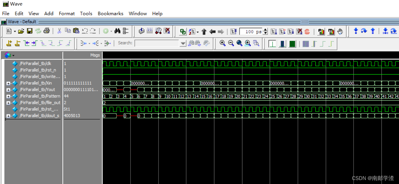
- 仿真波形图
3、使用matlabThe generated program is simulated and verified
- M程序:
%E4_7_NoiseAndCarrierOut.M
f1=200;       %信号1频率为200Hz
f2=800;       %信号2频率为800Hz
Fs=2000;      %采样频率为2KHz
N=12;         %量化位数

%从文本文件中读取数据
%Test input data are placed separatelyNoise_in和S_in变量中
fid=fopen('C:\matlab work\fir1_1\filterCoe\noise.txt','r');
[Noise_in,N_n]=fscanf(fid,'%lg',inf);
fclose(fid);

fid=fopen('C:\matlab work\fir1_1\filterCoe\sin.txt','r');
[S_in,S_n]=fscanf(fid,'%lg',inf);
fclose(fid);

%The filtered output result data are placed separatelyNoise_out和S_out变量中
fid=fopen('C:\matlab work\fir1_1\filterCoe\noise_out.txt','r');
[Noise_out,N_count]=fscanf(fid,'%lg',inf);
fclose(fid);

fid=fopen('C:\matlab work\fir1_1\filterCoe\sout.txt','r');
%fid=fopen('C:\matlab work\fir1_1\filterCoe\E4_7_Sout.txt','r');
[S_out,S_count]=fscanf(fid,'%lg',inf)
fclose(fid);

%归一化处理
Noise_out=Noise_out/max(abs(Noise_out));
S_out=S_out/max(abs(S_out));
Noise_in=Noise_in/max(abs(Noise_in));
S_in=S_in/max(abs(S_in));

%Find the amplitude-frequency response of the signal
out_noise=20*log10(abs(fft(Noise_out,1024))); out_noise=out_noise-max(out_noise);
out_s=20*log10(abs(fft(S_out(150:length(S_out)),1024))); out_s=out_s-max(out_s);

in_noise=20*log10(abs(fft(Noise_in,1024))); in_noise=in_noise-max(in_noise);
in_s=20*log10(abs(fft(S_in,1024))); in_s=in_s-max(in_s);
%The magnitude-frequency response of the filter itself
hn=black_fpga;
m_hn=20*log10(abs(fft(hn,1024))); m_hn=m_hn-max(m_hn);

%设置幅频响应的横坐标单位为Hz
x_f=[0:(Fs/length(out_noise)):Fs/2];
%Only the amplitude frequency response of the positive frequency part is displayed
mf_noise=out_noise(1:length(x_f));
mf_s=out_s(1:length(x_f));
mf_in_noise=in_noise(1:length(x_f));
mf_in_s=in_s(1:length(x_f));
mf_hn=m_hn(1:length(x_f));
%绘制幅频响应曲线
figure(1);
subplot(211);
plot(x_f,mf_in_noise,'--',x_f,mf_noise,'-',x_f,mf_hn,'--');
xlabel('频率(Hz)');ylabel('幅度(dB)');title('FPGASimulate the spectrum of a white noise signal before and after filtering');
legend('输入信号频谱','输出信号频谱','滤波器响应');
grid;
subplot(212);
plot(x_f,mf_in_s,'--',x_f,mf_s,'-',x_f,mf_hn,'--');
xlabel('频率(Hz)');ylabel('幅度(dB)');title('FPGASimulate the spectrum of the synthesized single-frequency signal before and after filtering');
axis([0 1000 -100 0]);
legend('输入信号频谱','输出信号频谱','滤波器响应');
grid;

%绘制时域波形
%Set the display data range
t=0:1/Fs:50/Fs;t=t*1000;
t_in_noise=Noise_in(1:length(t));
t_in_s=S_in(1:length(t));
t_out_noise=Noise_out(1:length(t));
t_out_s=S_out(1:length(t));
figure(2);
subplot(211);
plot(t,t_in_noise,'--',t,t_out_noise,'-');
xlabel('时间(ms)');ylabel('幅度');title('FPGASimulate the time domain waveform before and after filtering the white noise signal');
legend('Input signal waveform','输出信号波形');
grid;
subplot(212);
plot(t,t_in_s,'--',t,t_out_s,'-');
xlabel('时间(ms)');ylabel('幅度');title('FPGASimulate the time domain waveform before and after filtering the synthesized single frequency signal');
legend('Input signal waveform','输出信号波形');
grid;
- 仿真波形图
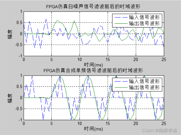

可以看到,parallel structureFIRThe filter design was successful,And the performance is better than the serial structure,设计成功.
边栏推荐
- 软件测试基本流程有哪些?北京专业第三方软件检测机构安利
- 《Show and Tell: A Neural Image Caption Generator》论文解读
- Especially the redis
- Redis源码:Redis源码怎么查看、Redis源码查看顺序、Redis外部数据结构到Redis内部数据结构查看源码顺序
- Daily sql - judgment + aggregation
- 每日sql -用户两天留存率
- Unity底层是如何处理C#的
- Redis源码-String:Redis String命令、Redis String存储原理、Redis字符串三种编码类型、Redis String SDS源码解析、Redis String应用场景
- Unity程序员如何提升自己的能力
- 你是如何做好Unity项目性能优化的
猜你喜欢
buu—Re(5)
Amazon Get AMAZON Product Details API Return Value Description
《Generative Adversarial Networks》
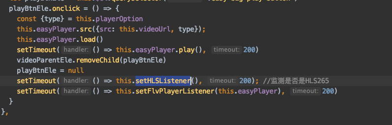
EasyPlayer针对H.265视频不自动播放设置下,loading状态无法消失的解决办法
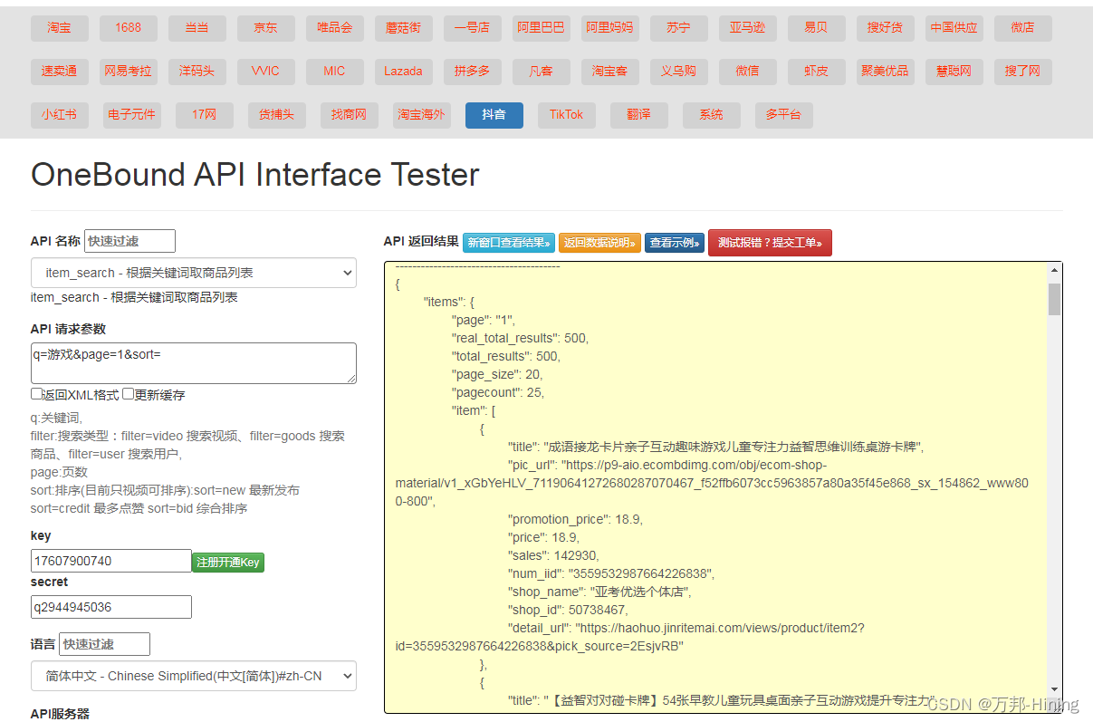
Trill keyword search goods - API
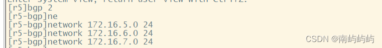
HCIP MPLS/BGP Comprehensive Experiment
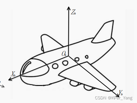
Coordinate system in navigation and positioning
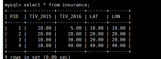
Daily sql-seek the sum of successful investments in 2016
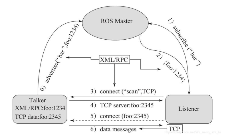
ROS 话题通信理论模型
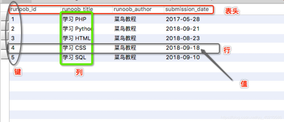
一个小时快速熟悉MySQL基本用法
随机推荐
每日sql-员工奖金过滤和回答率排序第一
图的拉普拉斯矩阵
亚马逊获得AMAZON商品详情 API 返回值说明
Pinduoduo API interface
基于FPGA的FIR滤波器的实现(5)— 并行结构FIR滤波器的FPGA代码实现
How Xshell connects to a virtual machine
Unity3D learning route?
opencv实现数据增强(图片+标签)平移,翻转,缩放,旋转
radix-4 FFT 原理和C语言代码实现
淘宝API常用接口与获取方式
【@网络工程师:用好这6款工具,让你的工作效率大翻倍!】
Taobao API common interface and acquisition method
numpy和tensor增加或删除一个维度
Especially the redis
NTT的Another Me技术助力创造歌舞伎演员中村狮童的数字孪生体,将在 “Cho Kabuki 2022 Powered by NTT”舞台剧中首次亮相
Trill keyword search goods - API
抖音关键词搜索商品-API工具
姿态解算-陀螺仪+欧拉法
Pinduoduo API interface (attach my available API)
每日sql:求好友申请通过率