当前位置:网站首页>SystemVerilog (VI) - variable
SystemVerilog (VI) - variable
2022-04-23 17:42:00 【Broken thoughts】

System Verilog Provide two sets of common data types : Networks and variables (nets and variables). Networks and variables have both type and data type characteristics . Type indicates that the signal is a network or variable , The data type represents the value system of the network or variable , namely 2 State or 4 state . For the sake of simplicity , Use the term data type To represent the type of signal and data type .
Software tools ( Such as emulators and integrated compilers ) Use data types to determine how to store data and process changes on data . Data types affect operations , And in RTL Used in modeling to indicate the desired silicon behavior . for example , The data type is used to determine whether the adder should be integer based or floating-point based , And whether signed arithmetic or unsigned arithmetic should be performed .
Network type and variable type
Variables are used as temporary storage for programming . This temporary storage is used for simulation . Actual silicon usually does not require the same temporary storage , It depends on the programming environment in which variables are used .SystemVerilog There are several types of variables , Will be discussed in the next section .
Networks are used to connect design blocks together , The network sends data values from the source ( Called driver ) Transfer to the destination or receiver driver .SystemVerilog Several network types are provided , This will be discussed in more detail later .
Two state and four state data types ( Bit and logic )
SystemVerilog The variable can be 2 Status data type or 4 Status data type . about 2 state , Each bit of a variable can have 0 or 1 Value , about 4 state , Each bit of a variable can have 0、1、Z or X Value .SystemVerilog The network can only be 4 Status data type . The keyword bit defines the variable as 2 Status data type . Keyword logic defines the variable or network as 4 Status data type .
Variable type
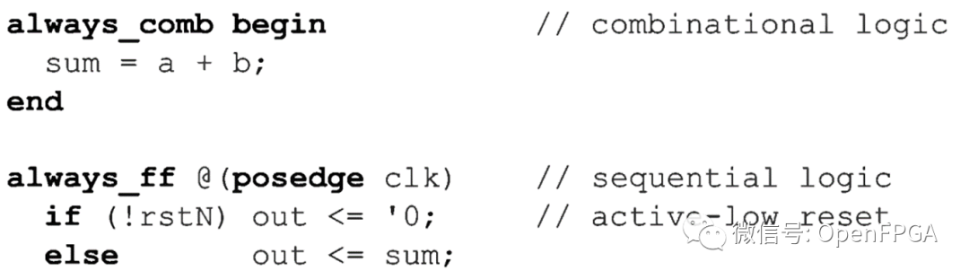
A variable is required on the left side of the block . The signal sum and output in the following code example must be variables .
Variables provide temporary storage for simulation .
In the previous code snippet always_comb The procedure will execute the assignment statement sum=a+b; Every time a or b When you change the value . Must be stored through the emulator sum Value , Until the next time a or b change . Similarly ,always_ff The process will be performed at each positive edge of the clock if-else Decision statement .out The value of must be stored by the simulator between clock cycles .
The temporary storage required by the simulator does not necessarily mean that the actual silicon needs to be stored . In the previous code snippet always_comb The process will be implemented in silicon as combinational logic . therefore , The value of the sum will continue to reflect the output of the adder , And does not require any type of hardware storage . On the other hand ,always_ff The program will be implemented in silicon as a trigger , A trigger is a hardware storage device .
Integrable variable data type
Declare variables by specifying both types and data types . Types can be specified explicitly or inferred implicitly , keyword var.
var Keywords are rarely used in practice SystemVeriIog The code uses . contrary ,var Types are inferred from other keywords and contexts .
SystemVerilog There are several keywords with built-in variable data types . These keywords infer var Logic (4 state ) or var position (2 state ) Variable type . Several variable data types represent the behavior of silicon , And it can be integrated . surface 3-1 Lists these integrable data types .
surface 3-1: Integrable variable data type| type | representative |
|---|---|
| reg | A general rule for user-defined vector sizes 4 State variable ; Equivalent to var logic |
| logic | It is common to infer user-defined vector sizes var logic 4 State variable , modular input/inout Except ports , In the module input/inout Infer on Port wire logic |
| integer | 32 position 4 State variables ; Equivalent to var logic [ 31: 0 ] |
| bit | General purpose with user-defined vector size 2 state var Variable ; If no size is specified , The default is 1 Bit size |
| int | 32 position 2 State variable ; amount to var bit[31 0]; Integrated compiler will int As 4 state integer Integer types |
| byte | 8 position 2 State variable ; Equivalent to var bit [ 7 : 0 ] |
| shortint | 16 position 2 State variable ; Equivalent to var bit [ 15: 0 ] |
| longint | 64 position 2 State variable ; Equivalent to var bit [ 63: 0 ] |
| Best practice guidelines 3-3 |
|---|
| Use 4 State logic data type inference RTL Variables in the model . Not in RTL Use... In the model 2 State type . An exception to this guideline is the use of int Type declaration for-loop Variables in iteration . |
Use 4 State variables allow the emulator to use when the value in the actual hardware is ambiguous X value .
Context sensitive logical data types .
In almost all contexts ,logic The data type infers a relationship with reg same 4 State variable . keyword logic It's not actually a variable type , It's a data type , Indicates that the network or variable can have 4 State value . however , When logic When the keyword is used alone or in combination with the declaration of the module output port , Can infer variables . When logic And input or inout When used in conjunction with port declarations , If logic Do not infer variables , The network type will be inferred .
Out of date reg data type
reg The data type is raw Verilog Outdated data types left over from the language . You should use logic Type, not reg. The original Verilog Language use reg The data type is used as a general variable .
Unfortunately , keyword reg The use of is a misnomer , It seems to be “register” Abbreviation , Registers are hardware devices built with triggers . actually , Use reg There is no correlation between variables and inferred hardware . The context of variables is used to determine whether the hardware represented is combinational logic or sequential trigger logic . Use logic Instead of reg Help prevent this misconception , That is, the hardware register will be inferred
X A value may indicate a design problem
When it appears during the simulation X When the value of , It usually indicates that there is a design problem . It can lead to X Some types of design errors for values include :
Registers not reset or otherwise initialized .
A circuit that does not hold state correctly in low power mode .
Unconnected module input port ( Unconnected input ports float at high impedance , When the high impedance value propagates to other logic , It usually produces X value ).
Multiple driver conflicts ( Bus contention ). Operations with unknown results .
Out of range bit selection and array index .
Establish or maintain a time conflict .
stay RTL Avoid using... In the model 2 Status data type .
bit、byte、shortint、int and longint The data type only stores 2 State value . These types cannot represent high impedance (Z value ), Can't be used X Value indicates an uninitialized or unknown simulation condition . When using 2 State data type , There will be no indication of potential design errors ( Such as the error in the above list ) Of X value . because 2 Status data type can only have one 0 or 1 value , Therefore, the wrong design in the simulation process may operate normally , That's not good. ! Use 2 The appropriate position of the state variable is to verify the random stimulus in the test-bed .
Non integrable variable types
SystemVerilog There are several types of variables that are mainly used for validation ,RTL These types are not usually supported by the synthesis compiler . surface 3-2 Lists these additional variable types . These data types are not used in any of the examples to be synthesized in this series .
surface 3-2: Non integrable variable data types| type | representative |
|---|---|
| real | Double precision floating point variable |
| shortreal | Single precision floating point variable |
| time | have timeunit and timeprecision Attribute 64 Bit unsigned 4 State variable |
| realtime | Double precision floating point variable ; And real As like as two peas |
| string | Storable 8 position ASCII Dynamic size array of byte type of character string |
| event | Pointer variable that stores the handle of the emulation synchronization object |
| class handle | Pointer variables that store class object handles ( The declaration type is the name of the class , Instead of keyword classes ) |
| chandle | A pointer variable , Used to store data from SystemVerilog Direct programming interface (DPI,Direct Programming Interface) The pointer passed to the simulation |
| virtual interface | Pointer variable for storing interface port handle (interface Keywords are optional ) |
The above types do not mean that they cannot be synthesized in any synthesizer , It only represents that it cannot be synthesized in most synthesizers .
Variable declaration rules
Variables are declared by specifying both types and data types , The type is keyword var, You can explicitly specify or implicitly infer .
| note |
|---|
| In practice SystemVeriIog Rarely used in code var keyword . contrary ,var Types are inferred from other keywords and contexts |
Some example variable declarations :
logic v1 // infer var logic(1 position 4 State variable )
bit v2; // infer var bit(1 position 2 State variable )
integer v3 // infer var integer(32 position 4 State variable )
int v4 // infer var int(32 position 2 State variable )
The only need is var The key word is to input perhaps inout The port is declared as 4 State variable . If not explicitly declared as a variable , Then these port directions will default to the network type , Input ports rarely need to be variables .
Scalar variables . A scalar variable is a 1 Bit variable .reg, logic and bit The default data type is 1 Bit scalar ,
Vector variables (packed arrays). A vector is an array of consecutive bits .IEEE SystemVerilog The standard calls vectors packet arrays (packed arrays). The reg, logic and bit Data types can represent vectors of any size : By referring to the scope of positioning in square brackets ([]), Followed by the vector name to declare the size of the vector . The scope is declared as [ Most significant digit number : Least significant digit number ]. Most significant bit (MSB) And least significant bit (LSB) It can be any number , also LSB Can be less than or greater than MSB.LSB A vector range that is a smaller number is called a small endpoint .LSB The range of vectors with larger values is called the big end
logic [31:0] v9;//32 Bit vector , Small end logic
logic [1:32] v10;;//32 Bit vector , Big end logic
RTL The most common convention in modeling is small end logic , And use 0 As a vector range LSB. These variables v9 Illustrates this practice . All the examples in this series use the small end logic Convention .
byte、shortint、int、longint and integer The data type has a predefined vector size , As shown in the table 3-1 Described . The predefined range is small end ,LSB The number is bit 0.
Signed and unsigned variables
In operation , Values stored in vector variables can be treated as signed or unsigned . Unsigned variables store only positive values . Signed variables can store positive and negative values .SystemVerilog Use 2 The complement of indicates a negative value . The most significant bit of a signed variable is the sign bit . When setting the symbol bit , The remaining bits of the vector represent negative values in the form of two complements .
By default ,reg、logic、bit and time The data type is an unsigned variable ,byte、shortint、int、integer and longint The data type is a signed variable . You can change this default value by explicitly declaring the variable signed or unsigned .

Constant bit selection and partial selection
Vectors can be referenced in whole or in part . Bit selects a single bit of the reference vector . Bit selection uses vector names , Followed by the tag in square brackets ([ ]) Partial selection refers to multiple consecutive bits of a vector . Partial selection uses vector names , Followed by a series of tags in square brackets ([ ])
Partial selection must meet two rules : The range of bits must be continuous , And partially selected endian Must be declared with a vector endian identical . The result of bit selection or partial selection is always unsigned , Even if the complete variable is signed .
Variable bit selection and partial selection . The bit selection in the previous code segment uses hard coded bit numbers . This is called fixed bit selection . The index number of bit selection can also be a variable . for instance .


The starting point of zero selection can also be variable . Zero selection can be incremented or decremented from the starting point of the variable . The total number of digits selected is a fixed range , The form of variable part selection is :

The second question is : The tag indicates that the tag number is incremented from the starting point . The mark indicates that the number decreases from the starting point tag .
The following example iterates with variable partial selection 32 Byte of bit vector .

Variable bit and partial selection can be integrated . however , As explained earlier, variable bits and partially selected code segments do not meet other requirements required by some integrated compilers RTL Coding restrictions .
Vectors with subfields . Define the vector range by using two or more sets of square brackets , You can declare vectors using subfields . The following code snippet shows a simple 32 Bit vectors and with subfields 32 The difference between bit vectors :

chart 3-1 It shows the difference between the two statements .
 chart 3-1: Vectors with subfields
Statement :

The first range [3 :0] Defines how many subfields are in the vector . In this case , There are four sub fields , The index for b [ 0 ],b [ l ],b [ 2 ], and b[3]. The second range [7:0] Defines the size of each subfield , In this case 8 position . chart 3-1 Explain the simple 32 The bit vector sum is subdivided into 4 Bytes of 32 Layout of bit vectors .
Subfields of a subdivision vector can be referenced using a single index rather than partial selection . The following code snippet demonstrates how to use a vector b Loop between bytes of , And it's simpler , Because each byte is a subfield of the vector .

Bit selection of subdivision vector requires multiple indexes - Select the vector b Bit of the third byte 7 Encoded as :b[3][7]
| Best practice guidelines 3-4 |
|---|
| When designing a single vector or a whole vector , Use simple vector declarations ; When the design often selects the part of the vector , Use vectors with subfields , And these parts are located on known boundaries , For example, byte or word boundaries . |
Select the subfield of the vector instead of using the fixed or variable part of a simple vector , It can make the code easier to write and maintain .
Variable allocation rules
Variables can be assigned in many ways :
As the left side of the procedure assignment statement ( stay always、always_comb、always_latch、always_ff Or in the initial process block , Or in a task or function ).
As the left side of the continuous assignment statement ( Use assign sentence ).
As a result of the assignment operator , for example ++ Incremental operators .
As a module 、 Input of tasks or functions .
As an example of a module 、 Task instance 、 The connection of the output port of the function instance or primitive instance .
Variables can only be assigned by a single source . for example , If the variable changes from assign In a continuous assignment statement , It is illegal to assign a value to a variable in the input port of a program block or module . however , Any number of program assignments to the same variable are considered a source . To make the following code work , This rule is very important :

stay RTL Modeling , Semantic constraints on the assignment of a single source variable are very important , This restriction helps ensure abstraction RTL The simulation behavior is the same as that after synthesis
always_ff,always_comb and always_latch The program block further limits the program assignment of variables to only one program , This enforces the requirements of the integrated compiler . Multiple assignments of variables in the same process are considered as a single driver .

Variable not initialized
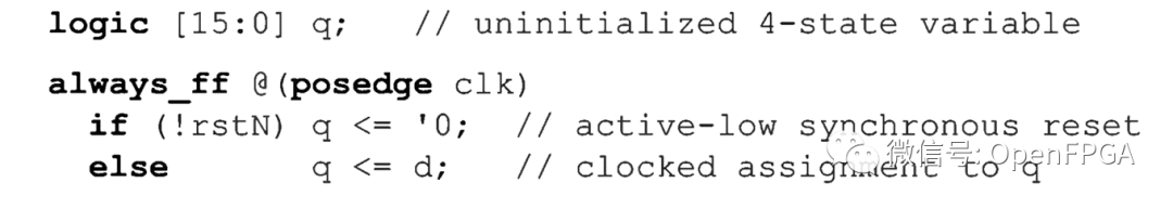
Before specifying a value for a variable , Variable not initialized .4 The uninitialized value of the state variable is X( All bits are set to x).2 The uninitialized value of the state variable is “0”( All bits are set to 0).
In the following example , until clk The first positive edge of appears , Variable q Is initialized . As a kind of 4 State logic type , Before the first clock ,q There will be a X value , here q Will be designated as 0 Value or d value . If clk The positive edge of does not appear , The X Values may indicate design problems , It may be due to clock gating or other conditions .
| note |
|---|
| Uninitialized 2 State variables can hide design problems . Uninitialized 2 The value of the state variable is 0, This may be a legal reset value . This may hide the problem of reset logic in the design . |
Online variable initialization
SystemVerilog Allows variables to be initialized when they are declared , Called online initialization . for example :

At the beginning of the simulation , The online initialization of variables is performed only once .
some FPGA The device can be programmed , Energize the register in a known state , Without resetting . Online variable initialization can be used to simulate these sequential devices ( Like triggers ) The power on state of .
| note |
|---|
| ASIC Technology does not support online variable initialization , some FPGA Technology may support online variable initialization . |
When for devices that do not support programmable power on Status , Integrated compiler will :(a) Online initialization is not allowed ,(b) Ignore it - When ignoring online initialization ,RTL Simulation behavior and integrated gate level implementation may not match ,
| Best practice guidelines 3-5 |
|---|
| Only when it will be used as FPGA Realized RTL The model is initialized with variables , And only model the power on of the trigger . |
about ASIC Design , The reset function should be used to initialize the variables . Do not use online initialization . about FPGA Design , Only when you're sure RTL When the model is always for devices that support power on register status , To use online initialization . stay RTL Use this type only to initialize the model effectively FPGA equipment .
| Best practice guidelines 3-6 |
|---|
| Only in RTL The model is initialized with embedded variables . Do not use the initialization procedure to initialize variables . |
A comprehensive compiler and target that supports online variable initialization FPGA The device also allows the initial process to be used to model the power on value of the trigger .

SystemVerilog( One )-RTL And gate level modeling

Digital hardware modeling -Verilog Stage summary and SystemVerilog Introduction

SystemVerilog( Two )-ASIC and FPGA Differences and modeling concepts

SystemVerilog( 3、 ... and )- Simulation

FPGA The relationship between synthesis and constraints

SystemVerilog( 5、 ... and )- Text value
版权声明
本文为[Broken thoughts]所创,转载请带上原文链接,感谢
https://yzsam.com/2022/04/202204231739402823.html
边栏推荐
- Hcip fifth experiment
- MySQL installation
- Exercise: even sum, threshold segmentation and difference (two basic questions of list object)
- Low code development platform sorting
- uni-app黑马优购项目学习记录(下)
- XTask与Kotlin Coroutine的使用对比
- 394. 字符串解码-辅助栈
- 开期货,开户云安全还是相信期货公司的软件?
- [difference between Oracle and MySQL]
- Header built-in object
猜你喜欢

SiteServer CMS5. 0 Usage Summary
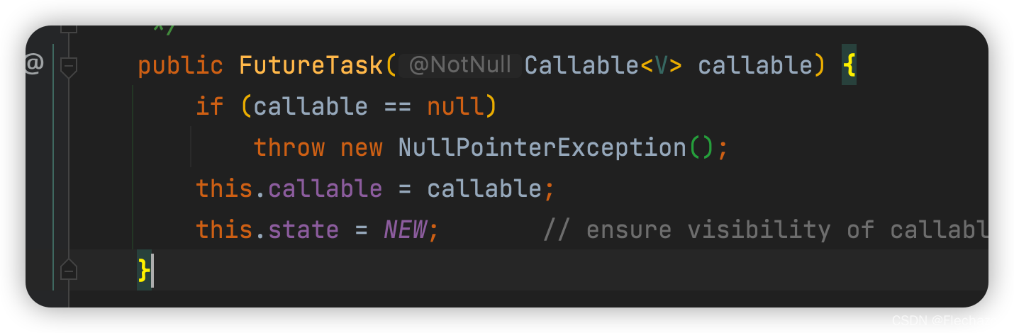
Future usage details
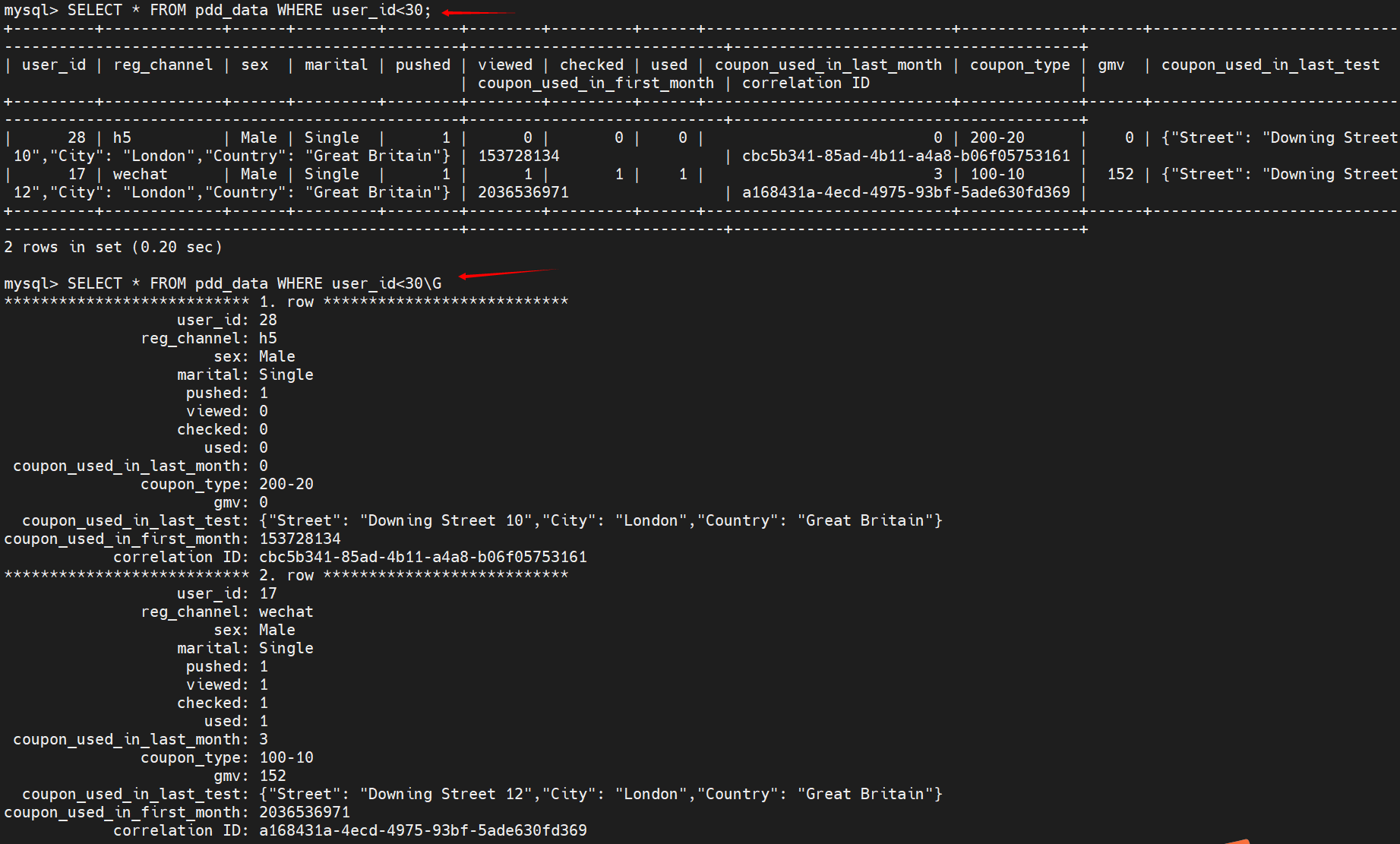
常用SQL语句总结
MySQL进阶之索引【分类,性能分析,使用,设计原则】
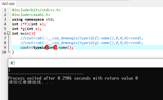
关于gcc输出typeid完整名的方法

If you start from zero according to the frame
102. 二叉树的层序遍历
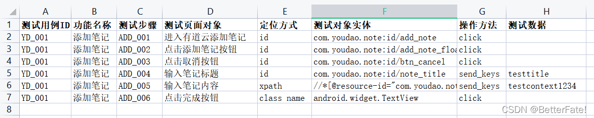
【Appium】通过设计关键字驱动文件来编写脚本
练习:求偶数和、阈值分割和求差( list 对象的两个基础小题)
![SQL optimization for advanced learning of MySQL [insert, primary key, sort, group, page, count]](/img/60/e4d47d458dd98a0c6ba51874e07c30.png)
SQL optimization for advanced learning of MySQL [insert, primary key, sort, group, page, count]
随机推荐
古代埃及希腊,数学用的什么进制
470. Rand10() is implemented with rand7()
XTask与Kotlin Coroutine的使用对比
Node template engine (EJS, art template)
How does matlab draw the curve of known formula and how does excel draw the function curve image?
For the space occupation of the software, please refer to the installation directory
[二叉数] 二叉树的最大深度+N叉树的最大深度
198. 打家劫舍-动态规划
Oninput one function to control multiple oninputs (take the contents of this input box as parameters) [very practical, very practical]
JS failed to change all variables and changed to the return method. Finally, the problem was solved
402. Remove K digits - greedy
MySQL进阶之索引【分类,性能分析,使用,设计原则】
土地覆盖/利用数据产品下载
Hcip fifth experiment
Index: teach you index from zero basis to proficient use
Advantages and disadvantages of several note taking software
Leak detection and vacancy filling (VIII)
圆环回原点问题-字节跳动高频题
[difference between Oracle and MySQL]
SQL optimization for advanced learning of MySQL [insert, primary key, sort, group, page, count]