当前位置:网站首页>51 MCU flowers, farmland automatic irrigation system development, proteus simulation, schematic diagram and C code
51 MCU flowers, farmland automatic irrigation system development, proteus simulation, schematic diagram and C code
2022-04-23 14:25:00 【Jiang Yuzhi】
The design requirements
1. Design a method based on 51 MCU flowers 、 Automatic farmland irrigation system ;
2. Able to detect soil moisture , When it is lower than the set lower limit , Start the water pump for irrigation , And provide corresponding audible and visual alarm indication ;
3. The upper and lower limits of humidity can be set by pressing the key ;
4. The soil moisture data and the upper and lower limits of moisture are passed LCD1602 The display shows ;
5. Complete the selection of system components 、 Circuit drawing and C Programming ;
System Overview
Design scheme of automatic watering irrigation system , With AT89C51 Single chip microcomputer is the control core , Using a modular design approach .
The components are :5V Power supply module 、 Soil moisture sensor module 、ADC0832 A / D conversion module 、 Water pump control module 、 Key input module 、LCD Display module and audible and visual alarm module , The structure is as follows .
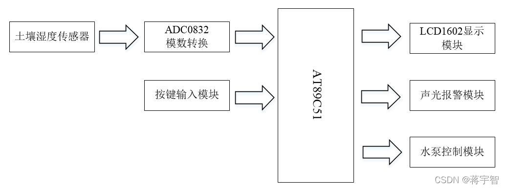
Working principle is : The soil moisture sensor measures the analog signal of soil moisture , the AD The converter converts the analog signal into digital signal and then transmits it to 51 Single chip microcomputer , The single chip microcomputer compares the soil moisture data with the set upper and lower limits .
When the soil moisture is below the lower limit , Drive the water pump for irrigation , And provide audible and visual alarm . When soil moisture increases above the lower limit , The audible and visual alarm is off , But the pump will continue to work , Until the soil moisture continues to increase and exceeds the set upper limit .
The user can set the upper and lower limits of humidity by pressing the key , The soil moisture data and the upper and lower limit data are passed LCD The display screen shows in real time .
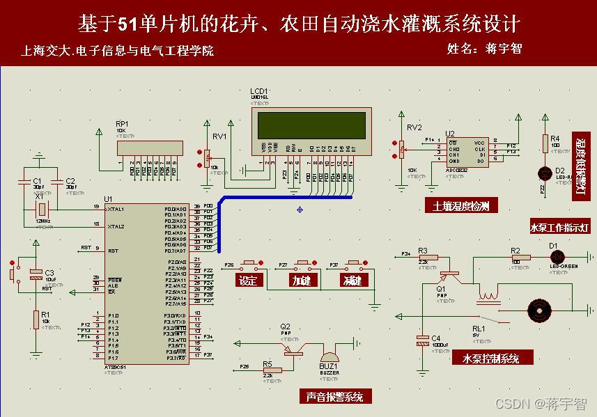
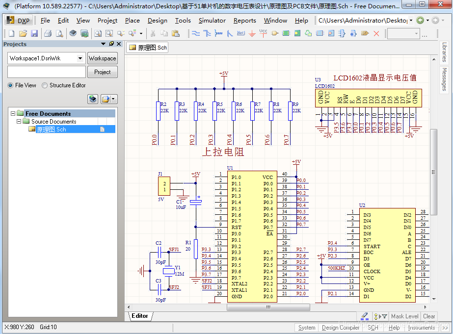
Schematic diagram
Simulation analysis
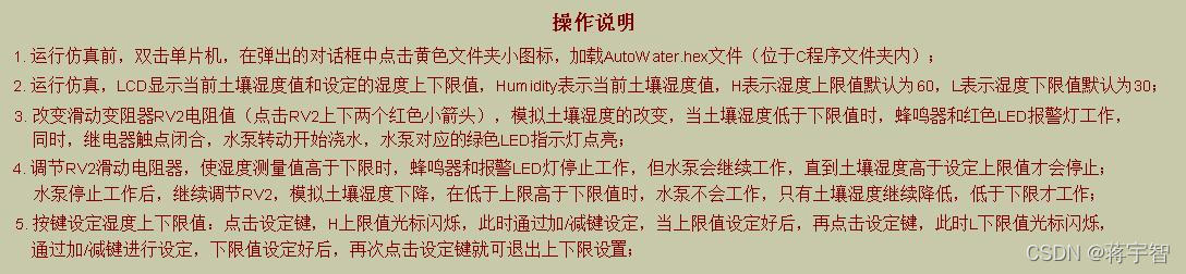
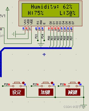
open Proteus Simulation file , Its suffix is .DSN. Double click the MCU , load AutoWater.hex file ( be located Keil C In the program folder ), Run the simulation , give the result as follows .
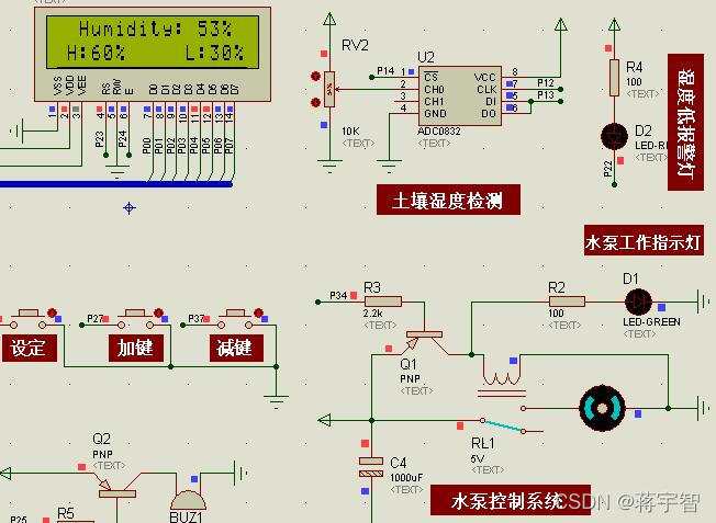
It can be seen from the picture that ,LCD Displays the currently measured soil moisture (Humidity) by 53%, The upper limit of humidity preset by the system (H:High Abbreviation ) by 60%, Lower limit (L:Low Abbreviation ) by 30%, The soil moisture is normal , Within the upper and lower limits .
here , Low humidity alarm light and buzzer are off , Relay RL1 Turn the switch to the bottom , The water pump is in a state of power failure .
By adjusting the sliding rheostat RV2( Click the two red arrows up and down with the mouse ), Change input to ADC0832 Sampling channels 0 To simulate the change of soil moisture .
Click on RV2 Downward red arrow , Simulate the reduction of soil moisture . for example , When the soil moisture changes from 53% Reduce to 23%, Below the lower limit 30% when , Red LED The warning lamp is on , The buzzer makes a sound , Relay RL1 Turn the switch to the top , The water pump is energized , Start automatic watering , The green water pump working indicator light is also on .

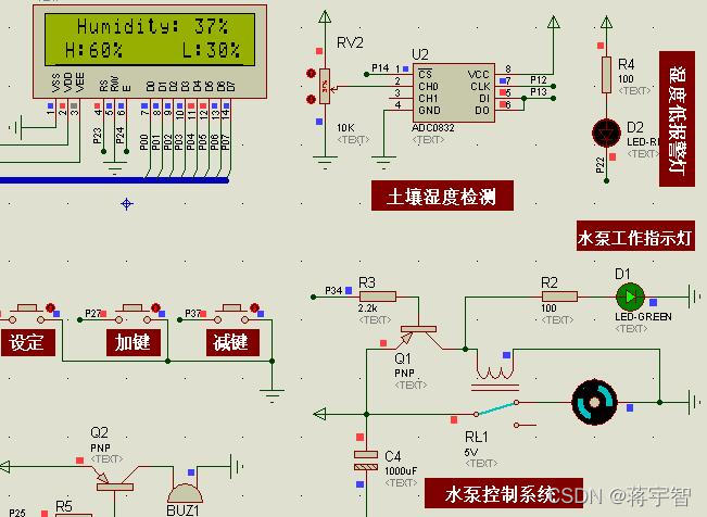
Click on RV2 The upward red arrow , Simulate the increase of soil moisture .
When the soil moisture changes from 23% Increased to 37%, When the lower limit is exceeded , The audible and visual alarm stops working , But the pump will continue to work , Until the soil moisture continues to increase above the upper limit , The process is as follows .
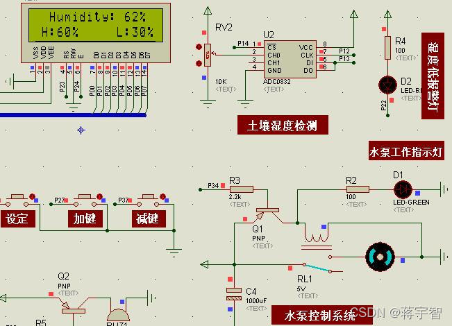
It should be noted that , The water pump stops working ( namely : Soil moisture exceeds the upper limit ) after , Adjust the RV2 Simulate the decline of soil moisture , When it falls within the upper and lower limits , The water pump will not start , Only when the soil moisture continues to drop below the lower limit will it start .
Press the key to preset the upper and lower limits of humidity .
Click on “ Set up ” key , Enter the upper and lower limit setting mode , First of all H The upper limit cursor flashes , At this point, you can click Add / Minus the key , Change the size of the upper limit .
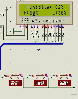
After the upper limit value is set , Click on “ Set up ” key ,L The lower limit cursor flashes , Empathy , Click Add / Minus the key , Change the size of the lower limit .
After the upper and lower limits are set , Click again on the “ Set up ” key , Exit the upper and lower limit setting mode . for example , We set the upper limit of humidity H by 75%, Lower limit L by 25%, The results are shown in the following figure .
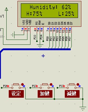
in summary , The simulation results meet the design requirements .
Part of the code
void main()				// The main function
{

	Init1602();						 // Initialize the LCD function
	init();							 // Initialize the timer
	init_eeprom();  // Start initializing the saved data
	while(1)						 // Into the loop
	{

		for(m=0;m<50;m++)			// read 50 Time AD value
			sum = adc0832(0)+sum;	// Read about AD value , Add the read data to the tired data sum
		temp=sum/50;				// Jump out of the top for After the cycle , Divide the total of the accumulation by 50 Get the average temp
		sum=0; 						// After the average calculation is completed , Clear the total
		temp = temp*0.390625;		//ADC0832 Store data as 1 Bytes , The humidity display range is 0~100, therefore 1 Unit humidity =100/256=0.390625
// if(temp<=full_range)
// temp=(temp*100)/full_range;
// else
// temp=100;
		if(set==0)					 //set by 0, It indicates that it is not in the setting state
			Display_1602(temp,MH,ML);// Show AD Values and alarm values
		if(temp<ML&&set==0)	         // The humidity value is less than the alarm value
		{

			flag=1;					 // Turn on the alarm
			Relay=0;					 // The relay contacts are closed , Water pump operation
			LED_R=0;					  // The red light is on
		}
		else if(temp>MH&&set==0)     // The humidity value is greater than the alarm value
		{

			flag=0;					 // Turn off the alarm
			Relay=1;					 // Relay contacts open , The water pump stops
			LED_R=1;					  // The red light goes out
		}
		else
		{

			flag=0;
			LED_R=1;			      // The red light goes out
		}
		Key();						 // Call the key function
	}
}
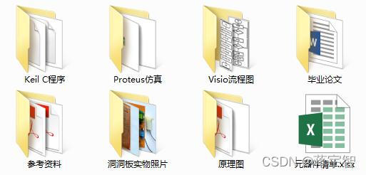
Information content
(1) be based on 51 Single chip microcomputer 、 Design of farmland automatic irrigation system ;
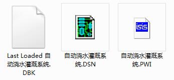
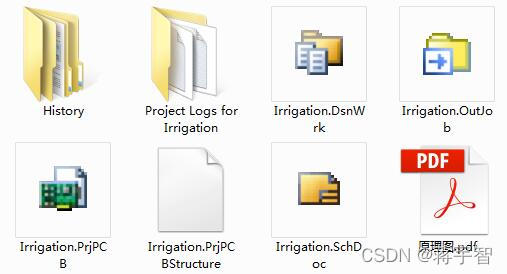
(2)Proteus Simulation file ;
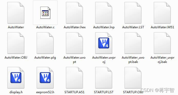
(3)C Program files ;
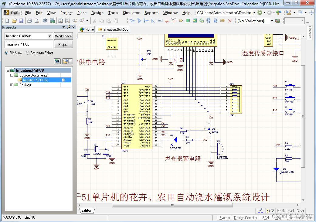
(4) Schematic file ;
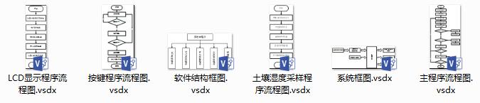
(5)Visio Flow chart file ;
(6) Reference material ;
(7) List of components ;
Data figure
Say the important thing again !!!
because 51 MCU flowers 、 The design of farmland automatic irrigation system is my original design , Get a full set of information ,
Please search to see my 【 Male 】( many *)“ Number ”: Jiaoyuan Xiaozhi
版权声明
本文为[Jiang Yuzhi]所创,转载请带上原文链接,感谢
https://yzsam.com/2022/04/202204231412471741.html
边栏推荐
- kprobe 的 3 种使用
- 查找水仙花数-for循环实践
- AT89C51单片机的数字电压表开发,量程0~5V,proteus仿真,原理图PCB和C程序等
- Nacos作为配置中心(四) 使用Demo
- Eight way responder system 51 Single Chip Microcomputer Design [with Proteus simulation, C program, schematic diagram, PCB files, component list and papers, etc.]
- Mysql的安装过程(已经安装成功的步骤说明)
- JumpServer
- 字节面试编程题:最小的K个数
- Use cases of the arrays class
- 微信小程序将原生请求通过es6的promise来进行优化
猜你喜欢

sar命令详解
API Gateway/API 网关(四) - Kong的使用 - 集成Jwt和熔断插件
AT89C51单片机的数字电压表开发,量程0~5V,proteus仿真,原理图PCB和C程序等
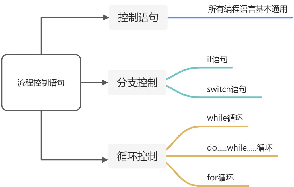
流程控制之分支语句

一篇博客让你学会在vscode上编写markdown
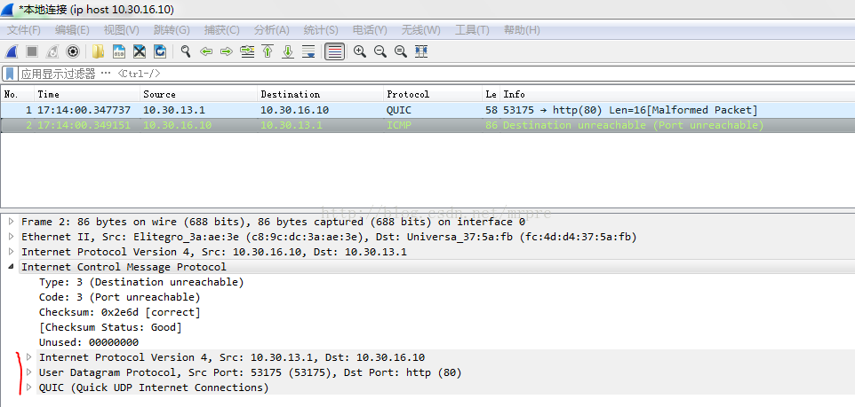
关于UDP接收icmp端口不可达(port unreachable)
XX project structure notes
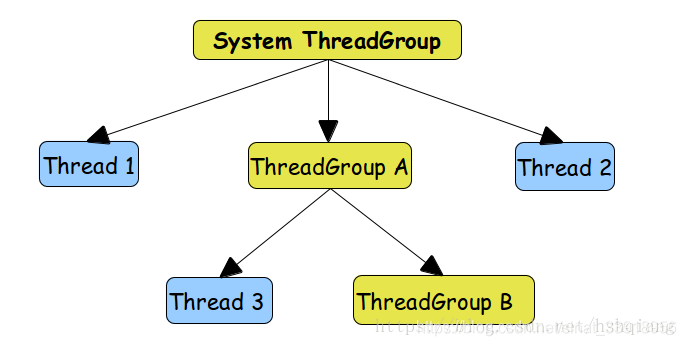
線程組ThreadGroup使用介紹+自定義線程工廠類實現ThreadFactory接口
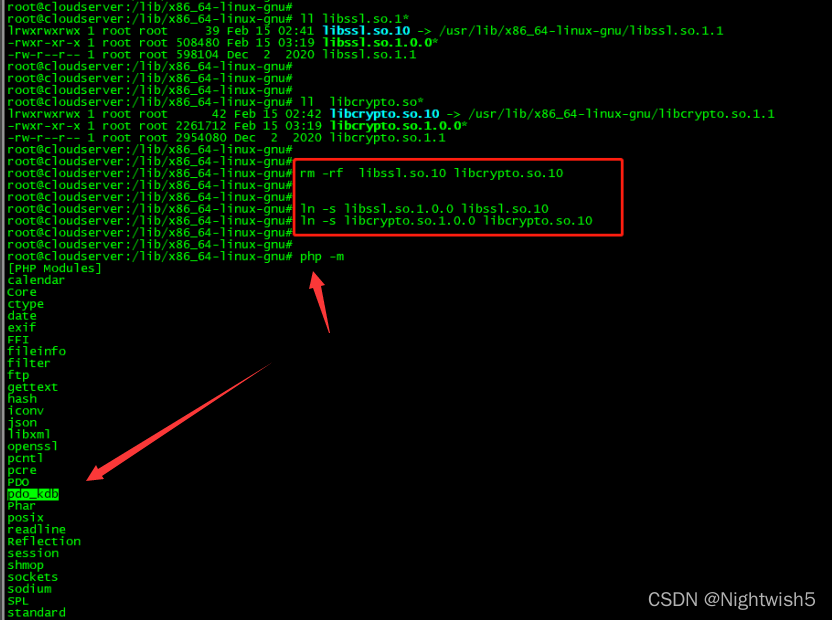
Tongxin UOS uninstall php7 2.24, install php7 4.27 ; Uninstall and then install PHP 7.2.34
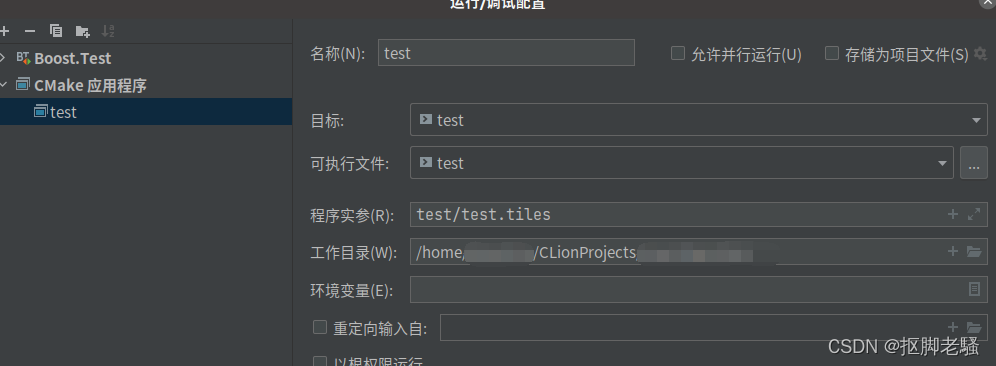
Pass in external parameters to the main function in clion
随机推荐
How to do a project easily
在电视屏幕上进行debug调试
xx项目架构随记
关于在vs中使用scanf不安全的问题
操作系统常见面试题目:
C语言p2选择分支语句详解
51单片机+LCD12864液晶显示的俄罗斯方块游戏,Proteus仿真、AD原理图、代码、论文等
C语言知识点精细详解——初识C语言【1】
Wechat applet rotation map swiper
asp.net使用MailMessage发送邮件的方法
MySQL同步Could not find first log file name in binary log index file错误
LLVM - 生成加法
Use cases of the arrays class
Qt实战:云曦日历篇
分分钟掌握---三目运算符(三元运算符)
矩阵交换行列
線程組ThreadGroup使用介紹+自定義線程工廠類實現ThreadFactory接口
DP - [noip2000] grid access
AT89C52单片机的频率计(1HZ~20MHZ)设计,LCD1602显示,含仿真、原理图、PCB与代码等
剑指offer刷题(2)--面向华为