当前位置:网站首页>The most detailed network counting experiment in history (2) -- rip experiment of layer 3 switch
The most detailed network counting experiment in history (2) -- rip experiment of layer 3 switch
2022-04-23 19:19:00 【It's quite bald, Qi Qi】
This blog continues to explain layer 3 switches and dynamic routing in computer networks RIP Protocol experiments .
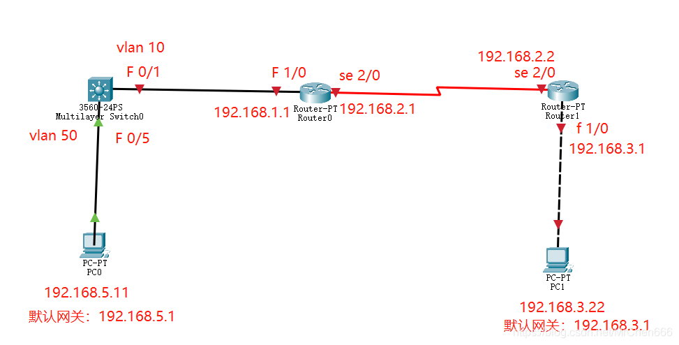
First, let's introduce the layer 3 switch , What we did before vlan The experiment uses a two-layer switch , Its function is to pc Connect the machine . On this basis, the layer 3 switch adds the function of connecting different LANs similar to routers , In LAN internal network, three-layer switch can be used to replace router , However, the interconnection between LAN and public network can not completely replace the work of router . What we used before vlan, When given a network number , In fact, it can represent a local area network .
Say again RIP agreement , Actually RIP The protocol is the algorithm that the router automatically configures the routing table . The static routing table we configured before requires us to manually enter , When multiple routers are connected, it will be very cumbersome , And when the connection is disconnected due to a problem with the line or equipment , The routing table can be adjusted dynamically , send pc Normal communication .


After talking about the principle , Let's start with the basics of the configuration experiment ip.
Layer 3 switch configuration :
Switch>en
Switch#conf t
Enter configuration commands, one per line.  End with CNTL/Z.
Switch(config)#vlan 10
Switch(config-vlan)#name v10
Switch(config-vlan)#exit
Switch(config)#vlan 50
Switch(config-vlan)#name v50
Switch(config-vlan)#exit
Switch(config)#int f0/5
Switch(config-if)#switchport access vlan 50 ## take f0/5 Port join vlan50
Switch(config-if)#exit
Switch(config)#int f0/1
Switch(config-if)#switchport access vlan 10
Switch(config-if)#exit
Switch(config)#
Router Router0 Set up :
Router>en
Router#conf t
Enter configuration commands, one per line.  End with CNTL/Z.
Router(config)#int f 1/0
Router(config-if)#ip addr 192.168.1.1 255.255.255.0 ## Set the port ip And mask
Router(config-if)#no sh ##no shutdown Abbreviation , Open port

Router(config-if)#
%LINK-5-CHANGED: Interface FastEthernet1/0, changed state to up

%LINEPROTO-5-UPDOWN: Line protocol on Interface FastEthernet1/0, changed state to up

Router(config-if)#exit
Router(config)#int se 2/0
Router(config-if)#ip addr 192.168.2.1 255.255.255.0
Router(config-if)#no sh

%LINK-5-CHANGED: Interface Serial2/0, changed state to down
Router(config-if)#exit
Router(config)#
The rest Router1 Also set as above , It's just a show here .
After configuring the above, let's start with the... In the layer 3 switch vlan No. configuration ip.
Switch#conf t
Enter configuration commands, one per line.  End with CNTL/Z.
Switch(config)#int vlan 10 ## Enter into vlan 10 And configure ip
Switch(config-if)#
%LINK-5-CHANGED: Interface Vlan10, changed state to up

%LINEPROTO-5-UPDOWN: Line protocol on Interface Vlan10, changed state to up

Switch(config-if)#ip addr 192.168.1.2 255.255.255.0 ## You can find that it is actually related to the port of the router ip equally , Its function is to interface vlan 10 The router address is 192.168.1.2 The interface of
Switch(config-if)#no sh
Switch(config-if)#exit
Switch(config)#int vlan 50
Switch(config-if)#
%LINK-5-CHANGED: Interface Vlan50, changed state to up

%LINEPROTO-5-UPDOWN: Line protocol on Interface Vlan50, changed state to up

Switch(config-if)#ip addr 192.168.5.1 255.255.255.0
Switch(config-if)#no sh
Switch(config-if)#exit
Switch(config)#ip routing ## This step is very important , Is equivalent to vlan in ip Update the information and put it in the table
Switch(config)#
We can check the success through the command .
Switch#show ip route
Codes: C - connected, S - static, I - IGRP, R - RIP, M - mobile, B - BGP
       D - EIGRP, EX - EIGRP external, O - OSPF, IA - OSPF inter area
       N1 - OSPF NSSA external type 1, N2 - OSPF NSSA external type 2
       E1 - OSPF external type 1, E2 - OSPF external type 2, E - EGP
       i - IS-IS, L1 - IS-IS level-1, L2 - IS-IS level-2, ia - IS-IS inter area
       * - candidate default, U - per-user static route, o - ODR
       P - periodic downloaded static route

Gateway of last resort is not set

C    192.168.1.0/24 is directly connected, Vlan10      ## These two lines indicate success
C    192.168.5.0/24 is directly connected, Vlan50

Switch#
End of configuration vlan Of ip after , We can divide different LANs and communicate through three-tier switches , Next, turn on the layer 3 switch and router RIP agreement .
The network number of each network segment :

First, turn on the protocol of the layer 3 switch :
Switch#en
Switch#conf t
Enter configuration commands, one per line.  End with CNTL/Z.
Switch(config)#router rip ## Configuration command
Switch(config-router)#network 192.168.1.0 ## Declare the direct network segment of this machine
Switch(config-router)#network 192.168.5.0
Switch(config-router)#exit
Switch(config)#
Next, the router Router 0 Open agreement :
Router>en
Router#conf t
Enter configuration commands, one per line.  End with CNTL/Z.
Router(config)#router rip
Router(config-router)#network 192.168.1.0
Router(config-router)#network 192.168.2.0
Router(config-router)#exit
Router(config)#
Router Router 1 similar , There's no show here . When we're done, let's look at the routing table .
Three layer switch :
Switch#show ip route
Codes: C - connected, S - static, I - IGRP, R - RIP, M - mobile, B - BGP
       D - EIGRP, EX - EIGRP external, O - OSPF, IA - OSPF inter area
       N1 - OSPF NSSA external type 1, N2 - OSPF NSSA external type 2
       E1 - OSPF external type 1, E2 - OSPF external type 2, E - EGP
       i - IS-IS, L1 - IS-IS level-1, L2 - IS-IS level-2, ia - IS-IS inter area
       * - candidate default, U - per-user static route, o - ODR
       P - periodic downloaded static route

Gateway of last resort is not set

C    192.168.1.0/24 is directly connected, Vlan10
R    192.168.2.0/24 [120/1] via 192.168.1.1, 00:00:18, Vlan10  ## Yes R These two items indicate success
R    192.168.3.0/24 [120/2] via 192.168.1.1, 00:00:18, Vlan10
C    192.168.5.0/24 is directly connected, Vlan50

Switch#
Router 0 Routing table :
Router#show ip route
Codes: C - connected, S - static, I - IGRP, R - RIP, M - mobile, B - BGP
       D - EIGRP, EX - EIGRP external, O - OSPF, IA - OSPF inter area
       N1 - OSPF NSSA external type 1, N2 - OSPF NSSA external type 2
       E1 - OSPF external type 1, E2 - OSPF external type 2, E - EGP
       i - IS-IS, L1 - IS-IS level-1, L2 - IS-IS level-2, ia - IS-IS inter area
       * - candidate default, U - per-user static route, o - ODR
       P - periodic downloaded static route

Gateway of last resort is not set

C    192.168.1.0/24 is directly connected, FastEthernet1/0
C    192.168.2.0/24 is directly connected, Serial2/0
R    192.168.3.0/24 [120/1] via 192.168.2.2, 00:00:18, Serial2/0
R    192.168.5.0/24 [120/1] via 192.168.1.2, 00:00:16, FastEthernet1/0

Router#
And then pc See if you can ping through .

ping The experiment proved our success , If you do real machine experiments , I'm still saying , Remember to turn off the firewall !
版权声明
本文为[It's quite bald, Qi Qi]所创,转载请带上原文链接,感谢
https://yzsam.com/2022/04/202204210600172028.html
边栏推荐
- Intuitive understanding of the essence of two-dimensional rotation
- Partage de la conception de l'alimentation électrique de commutation et illustration des compétences en conception de l'alimentation électrique
- SSDB基础
- Using 8266 as serial port debugging tool
- What is a message queue
- SSDB foundation 3
- 2022.04.23(LC_714_买卖股票的最佳时机含手续费)
- Openlayers 5.0 reload the map when the map container size changes
- How about CICC wealth? Is it safe to open an account up there
- Openharmony open source developer growth plan, looking for new open source forces that change the world!
猜你喜欢

Wechat video extraction and receiving file path

Keysight has chosen what equipment to buy for you
arcMap 发布切片服务
Oracle configuration st_ geometry

Using oes texture + glsurfaceview + JNI to realize player picture processing based on OpenGL es
An idea of rendering pipeline based on FBO
Reflection on the performance of some OpenGL operations in the past

RuntimeError: Providing a bool or integral fill value without setting the optional `dtype` or `out`

Common SQL commands
Pdf reference learning notes
随机推荐
Coordinate conversion WGS-84 to gcj-02 and gcj-02 to WGS-84
高层次人才一站式服务平台开发 人才综合服务平台系统
Oracle配置st_geometry
openlayers 5.0 热力图
腾讯云GPU最佳实践-使用jupyter pycharm远程开发训练
How to uninstall easyton
Regular expressions for judging positive integers
Pdf reference learning notes
JS to get the local IP address
2022.04.23 (the best time for lc_714_to buy and sell stocks, including handling charges)
剑指 Offer II 116. 省份数量-空间复杂度O(n),时间复杂度O(n)
std::stoi stol stoul stoll stof stod
openlayers 5.0 当地图容器大小改变时,重新加载地图
SSDB基础1
What is a message queue
ArcGIS JS API dojoconfig configuration
Network protocol: SCTP flow control transmission protocol
Raspberry pie 18b20 temperature
Encyclopedia of professional terms and abbreviations in communication engineering
什么是消息队列