当前位置:网站首页>Quartus prime hardware experimental development (de2-115 board) experiment II function adjustable comprehensive timer design
Quartus prime hardware experimental development (de2-115 board) experiment II function adjustable comprehensive timer design
2022-04-23 13:56:00 【Slag Ye】
Experiment 2 design of function adjustable comprehensive timer
- The experiment purpose
- master QuartusII And other experimental tools 、 comprehensive 、 Simulation 、 How to use the download
- master DE2 The functional characteristics and application methods of the developed version of the device
- master Verilog HDL The main methods and techniques of sequential logic system design
- Master and apply EDA Design method and process
- Preview requirements
- understand QuartusII Equal Discipline Distribution 、 Download method and process
- Understand the input of development board 、 The output shows the working characteristics of the resource
- Understand development board design 、 Development and testing methods and processes
- The experimental requirements
Design an adjustable integrated timer . Specific function :
- Show hours 、 branch 、 second , Provide zero setting function . Displayed in seven section pipe or LCD On the screen , You can consider 24/12 Hour mode switching function .
- Capable of measuring seconds 、 branch 、 Hours are modified separately , It can be modified as a whole with two digits or independently with each digit
- The hour report function , The whole point can show a certain form of LED To express .
- Alarm function , Set a specific time , Arrive at a specific time LED Display to display the alarm clock . Pay attention to the duration of the alarm clock , You can also refer to the lazy alarm clock mode .
The initial operation is almost similar to experiment 1 , Please refer to Experiment 1 link :Quartus Prime Hardware experimental development (DE2-115 plate ) Experiment 1 CPU Instruction arithmetic unit design _ Slag ye The blog of -CSDN Blog
It should be noted that , In Experiment 2 , need Replace the value corresponding to the pin , The specific value table is linked as follows :
The main body of code :
module shizhong(clkin,key0,hex0,hex1,hex2,hex3,hex4,hex5,hex6,hex7,KEY0,KEY1,key17,key16,key15,LEDR,LEDG,in,key14,key13,key12);
input clkin;
input key0,key17,key16,key15,key14,key13,key12;
input[6:1] in;
input KEY0,KEY1;
reg clk=0;
output reg[6:0] hex0,hex1,hex2,hex3,hex4,hex5,hex6,hex7;
output reg[7:0] LEDR,LEDG;
reg[7:0] out2,out3,out4,out5,out6,out7;
reg[7:0] second;
reg[7:0] minute;
reg[7:0] hour;
reg[7:0] second1;
reg[7:0] minute1;
reg[7:0] hour1;
integer N=25000000;
integer i=0;
reg[16:0] naozhong=0;
reg[16:0] s=0;
integer a=86400;

always@(posedge clkin) // frequency division
begin
if(i==N)
	begin
		i=0;
		clk=~clk;
	end
else i=i+1;
end

always@(posedge clk)
begin
if(key0) s=0; // Zeroing
else
// Count
begin
// It's time for the hour
if(s%3600==0)
begin
LEDR=8'b11111111;
end
else
	begin
		LEDR=8'b00000000;
		s=(s+1)%a;
	end
if(key17&&key16==0&&key15==0) // Adjust the hours
	begin
		if(KEY0==0)s=(s+3600)%a;
		else if(KEY1==0)s=(s-3600)%a;
		else s=s%a;
	end
else if(key17==0&&key16&&key15==0)   // Adjust the minutes
	begin
		if(KEY0==0)s=(s+60)%a;
		else if(KEY1==0)s=(s-60)%a;
		else s=s%a;
	end
else if(key17==0&&key16==0&&key15)   // Adjust the second
	begin
		if(KEY0==0)s=(s+1)%a;

		else if(KEY1==0)s=(s-1)%a;
		else s=s%a;
	end
end
end


always@(key17,key16,key15,s)
begin
// alarm clock
if(key17==1&&key16==1&&key15==1)
	begin
		naozhong = 0;
		if(key12)naozhong=naozhong+in;
		else if(key13)naozhong=naozhong+in*60;
		else if(key14)naozhong=naozhong+in*3600;
		else naozhong=naozhong;

		second1=naozhong%60;
		minute1=naozhong/60%60;
		hour1=naozhong/3600;
		out7=hour1/10;
		out6=hour1%10;
		out5=minute1/10;
		out4=minute1%10;
		out3=second1/10;
		out2=second1%10;
		hex7=seven(out7);
		hex6=seven(out6);
		hex5=seven(out5);
		hex4=seven(out4);
		hex3=seven(out3);
		hex2=seven(out2);
		hex1=7'b1111111;
		hex0=7'b1111111;
	end
else
	begin
		second=s%60;minute=s/60%60;hour=s/3600;
		out7=hour/10;out6=hour%10;
		out5=minute/10;out4=minute%10;
		out3=second/10;out2=second%10;
		hex7=seven(out7);
		hex6=seven(out6);
		hex5=seven(out5);
		hex4=seven(out4);
		hex3=seven(out3);
		hex2=seven(out2);
		hex1=7'b1111111;
		hex0=7'b1111111;
	if(s==naozhong)LEDG=8'b11111111;
	else LEDG=8'b00000000;
	end

end


function[6:0] seven;
input [7:0] din;
case(din)
	4'h0:seven=7'b1000000;
	4'h1:seven=7'b1111001;
	4'h2:seven=7'b0100100;
	4'h3:seven=7'b0110000;
	4'h4:seven=7'b0011001;
	4'h5:seven=7'b0010010;
	4'h6:seven=7'b0000010;
	4'h7:seven=7'b1111000;
	4'h8:seven=7'b0000000;
	4'h9:seven=7'b0010000;
	default:seven=7'b1111111;
endcase
endfunction
endmodule
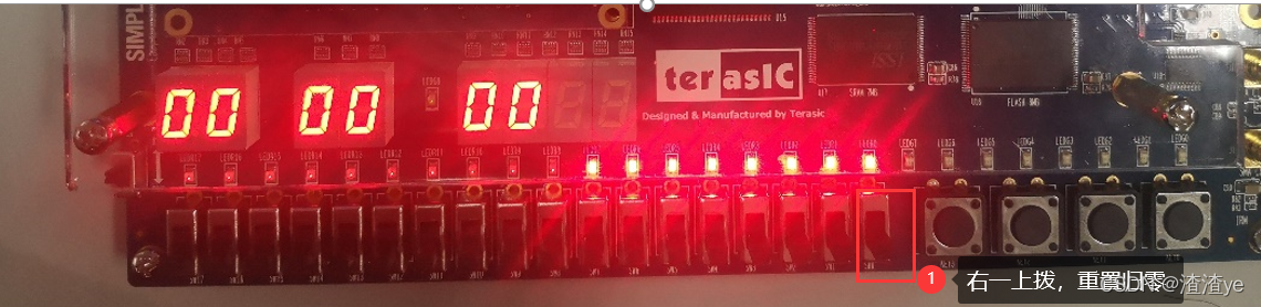
Hardware testing :
Zeroing
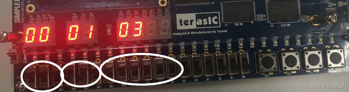
Control time

set alarm , Time out , The green light is on

版权声明
本文为[Slag Ye]所创,转载请带上原文链接,感谢
https://yzsam.com/2022/04/202204231353463415.html
边栏推荐
- Reading notes: meta matrix factorization for federated rating predictions
- Leetcode | 38 appearance array
- Window analysis function last_ VALUE,FIRST_ VALUE,lag,lead
- Oracle database recovery data
- Three characteristics of volatile keyword [data visibility, prohibition of instruction rearrangement and no guarantee of operation atomicity]
- Detailed explanation and usage of with function in SQL
- JS brain burning interview question reward
- 大专的我,闭关苦学 56 天,含泪拿下阿里 offer,五轮面试,六个小时灵魂拷问
- Oracle generates millisecond timestamps
- Oracle database combines the query result sets of multiple columns into one row
猜你喜欢
![MySQL index [data structure + index creation principle]](/img/11/6bdc8a62e977ffb67be07ded0c8978.png)
MySQL index [data structure + index creation principle]
elmo(BiLSTM-CRF+elmo)(Conll-2003 命名实体识别NER)

Express middleware ③ (custom Middleware)

Static interface method calls are not supported at language level '5'

Jenkins construction and use

Lenovo Saver y9000x 2020
记录一个奇怪的bug:缓存组件跳转之后出现组件复制

2022年江西最新建筑八大员(质量员)模拟考试题库及答案解析

自动化的艺术
神经元与神经网络
随机推荐
聯想拯救者Y9000X 2020
freeCodeCamp----arithmetic_ Arranger exercise
MySQL [acid + isolation level + redo log + undo log]
村上春树 --《当我谈跑步时,我谈些什么》句子摘录
Analysis of redo log generated by select command
蓝绿发布、滚动发布、灰度发布,有什么区别?
[machine learning] Note 4. KNN + cross validation
ACFs file system creation, expansion, reduction and other configuration steps
Haruki Murakami -- Excerpt from "what do I talk about when I talk about running"
Small case of web login (including verification code login)
专题测试05·二重积分【李艳芳全程班】
Tensorflow & pytorch common error reporting
Postman reference summary
Troubleshooting of expdp export error when Oracle table has logical bad blocks
Window function row commonly used for fusion and de duplication_ number
19c RAC steps for modifying VIP and scanip - same network segment
[code analysis (4)] communication efficient learning of deep networks from decentralized data
Oracle defines self incrementing primary keys through triggers and sequences, and sets a scheduled task to insert a piece of data into the target table every second
2022年江西最新建筑八大员(质量员)模拟考试题库及答案解析
SQL learning | set operation