当前位置:网站首页>Laser slam theory and practice of dark blue College Chapter 3 laser radar distortion removal exercise
Laser slam theory and practice of dark blue College Chapter 3 laser radar distortion removal exercise
2022-04-23 17:51:00 【ppipp1109】
1. Supplement the code of removing lidar motion distortion module ;
Code description of question 1 :
This topic is to realize a code module for odometer to remove lidar motion distortion , There are two projects in the homework :
champion_nav_msgs and LaserUndistortion. You need to compile and install first champion_nav_msgs, according to
champion_nav_msgs Of readme File execution , Or run the command sudo bash install.sh, Notice if your
ubuntu The version is not kinetic, To put all kinetic Change the place to your ros edition .
The running process of the program is :
Step1: Realization 207 That's ok LidarMotionCalibration function , And use catkin_make Command to compile ;
Step2: stay LaserUndistortion Next , Conduct source:source devel/setup.bash;
Step3: function launch file :roslaunch LaserUndistortion LaserUndistortion.launch, When executing this instruction , There must be no ROS The node is running , roscore And shut it down ;
Step4: Enter into /bag Under the table of contents , Operation instruction :rosbag play -–clock laser.bag;
Step5: If everything goes well , You will see pcl The visual world of
Their thinking :
Using interpolation , So as to get the posture of each small moment , So as to remove motion distortion .
Define several physical quantities :
(1)start_time : When the laser data starts .
(2)end_time : endTime = startTime + ros::Duration(laserScanMsg.time_increment * beamNum); When the laser data ends .
(3)frame_start_pose : Radar data start time , from odom Acquired start_time Robot posture at all times .
(4)frame_mid_pose : Radar time of a frame in the middle , from odom Acquired mid_time Robot posture at all times .
(5)frame_end_pose : Radar data end time , from odom Acquired end_time Robot posture at all times .
(6)frame_base_pose : Datum coordinates , Is to put all the de distorted electric clouds in this coordinate system . Here we take the pose of the first radar data as the reference coordinate .( Reference pose )
(7)interpolation_time_duration : Interpolation interval . If mid_time - start_time > interpolation_time_duration, Then interpolate .
(8)interp_count : There are several laser points in the interpolation interval .
Coordinate conversion process :
Lidar coordinate system --> Visual odometer coordinate system --> Basic coordinate system
The idea of interpolation :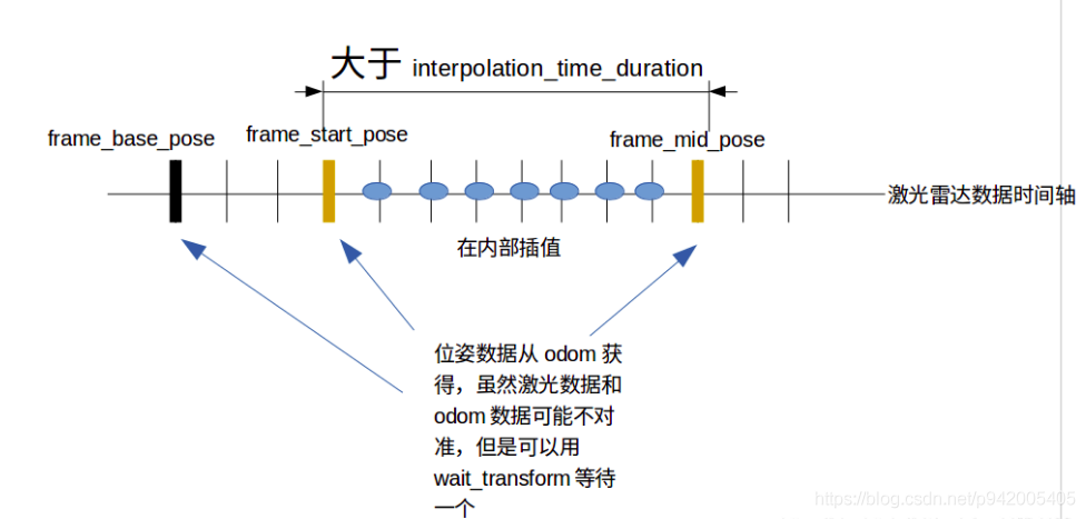
Each time, select a laser time period in the middle that exceeds the interpolation time , Starting from start, The finish for middle, The position and attitude of the beginning and end of this segment are obtained by odometer , It can be used !tf_->waitForTransform("/odom", “/base_laser”, dt, ros::Duration(0.5))) Wait for one , Avoid the problem of time synchronization . Interpolate the interior , There are several interpolation points , So that each laser point has its own pose .
All source code
#include <ros/ros.h>
#include <tf/tf.h>
#include <tf/transform_broadcaster.h>
#include <tf/transform_listener.h>

#include <sensor_msgs/LaserScan.h>

#include <champion_nav_msgs/ChampionNavLaserScan.h>

#include <pcl-1.8/pcl/point_cloud.h>
#include <pcl-1.8/pcl/visualization/cloud_viewer.h>
#include <pcl/point_types.h>

#include <dirent.h>
#include <fstream>
#include <iostream>

pcl::visualization::CloudViewer g_PointCloudView("PointCloud View");

class LidarMotionCalibrator {
public:
    LidarMotionCalibrator(tf::TransformListener* tf)
    {
        tf_ = tf;
        scan_sub_ = nh_.subscribe("champion_scan", 10, &LidarMotionCalibrator::ScanCallBack, this);
    }

    ~LidarMotionCalibrator()
    {
        if (tf_ != NULL)
            delete tf_;
    }

    //  Get the original laser data for processing
    void ScanCallBack(const champion_nav_msgs::ChampionNavLaserScanPtr& scan_msg)
    {
        // Convert to the data needed for correction
        ros::Time startTime, endTime;
        startTime = scan_msg->header.stamp;

        champion_nav_msgs::ChampionNavLaserScan laserScanMsg = *scan_msg;

        // Time to get the final point
        int beamNum = laserScanMsg.ranges.size();
        endTime = startTime + ros::Duration(laserScanMsg.time_increment * beamNum);

        //  Copy the data
        std::vector<double> angles, ranges;
        for (int i = beamNum - 1; i > 0; i--) {
            double lidar_dist = laserScanMsg.ranges[i];
            double lidar_angle = laserScanMsg.angles[i];

            if (lidar_dist < 0.05 || std::isnan(lidar_dist) || std::isinf(lidar_dist))
                lidar_dist = 0.0;

            ranges.push_back(lidar_dist);
            angles.push_back(lidar_angle);
        }

        // Convert to pcl::pointcloud for visuailization

        tf::Stamped<tf::Pose> visualPose;
        if (!getLaserPose(visualPose, startTime, tf_)) {
            ROS_WARN("Not visualPose,Can not Calib");
            return;
        }

        double visualYaw = tf::getYaw(visualPose.getRotation());

        visual_cloud_.clear();
        for (int i = 0; i < ranges.size(); i++) {

            if (ranges[i] < 0.05 || std::isnan(ranges[i]) || std::isinf(ranges[i]))
                continue;

            double x = ranges[i] * cos(angles[i]);
            double y = ranges[i] * sin(angles[i]);

            pcl::PointXYZRGB pt;
            pt.x = x * cos(visualYaw) - y * sin(visualYaw) + visualPose.getOrigin().getX();
            pt.y = x * sin(visualYaw) + y * cos(visualYaw) + visualPose.getOrigin().getY();
            pt.z = 1.0;

            // pack r/g/b into rgb
            unsigned char r = 255, g = 0, b = 0; //red color
            unsigned int rgb = ((unsigned int)r << 16 | (unsigned int)g << 8 | (unsigned int)b);
            pt.rgb = *reinterpret_cast<float*>(&rgb);

            //  The position and pose of the original data point cloud under the odometer coordinate system , Because without correction ,
            //  The laser spot halo of a frame is considered to be recorded at the same position as the laser spot of the starting point ( So it's like the laser doesn't move , In fact, the laser is moving , This produces distortion )
            visual_cloud_.push_back(pt);
        }
        std::cout << std::endl;

        // To correct
        Lidar_Calibration(ranges, angles,
            startTime,
            endTime,
            tf_);

        // Convert to pcl::pointcloud for visuailization
        for (int i = 0; i < ranges.size(); i++) {

            if (ranges[i] < 0.05 || std::isnan(ranges[i]) || std::isinf(ranges[i]))
                continue;

            double x = ranges[i] * cos(angles[i]);
            double y = ranges[i] * sin(angles[i]);

            pcl::PointXYZRGB pt;
            pt.x = x * cos(visualYaw) - y * sin(visualYaw) + visualPose.getOrigin().getX();
            pt.y = x * sin(visualYaw) + y * cos(visualYaw) + visualPose.getOrigin().getY();
            pt.z = 1.0;

            unsigned char r = 0, g = 255, b = 0; // green color
            unsigned int rgb = ((unsigned int)r << 16 | (unsigned int)g << 8 | (unsigned int)b);
            pt.rgb = *reinterpret_cast<float*>(&rgb);

            visual_cloud_.push_back(pt);
        }

        // Display
        g_PointCloudView.showCloud(visual_cloud_.makeShared());
    }

    /**
     * @name getLaserPose()
     * @brief  Get the pose of the robot in the odometer coordinate system tf::Pose
     *         obtain dt At the moment, the lidar is odom The pose of the coordinate system
     * @param odom_pos   The pose of the robot
     * @param dt        dt moment
     * @param tf_
    */
    bool getLaserPose(tf::Stamped<tf::Pose>& odom_pose,
        ros::Time dt,
        tf::TransformListener* tf_)
    {
        odom_pose.setIdentity();

        tf::Stamped<tf::Pose> robot_pose;
        robot_pose.setIdentity();
        robot_pose.frame_id_ = "base_laser";
        robot_pose.stamp_ = dt; // Set to ros::Time() Indicates that the most recent conversion relationship is returned

        // get the global pose of the robot
        try {
            if (!tf_->waitForTransform("/odom", "/base_laser", dt, ros::Duration(0.5))) // 0.15s  The time can be modified
            {
                ROS_ERROR("LidarMotion-Can not Wait Transform()");
                return false;
            }
            tf_->transformPose("/odom", robot_pose, odom_pose);
        } catch (tf::LookupException& ex) {
            ROS_ERROR("LidarMotion: No Transform available Error looking up robot pose: %s\n", ex.what());
            return false;
        } catch (tf::ConnectivityException& ex) {
            ROS_ERROR("LidarMotion: Connectivity Error looking up looking up robot pose: %s\n", ex.what());
            return false;
        } catch (tf::ExtrapolationException& ex) {
            ROS_ERROR("LidarMotion: Extrapolation Error looking up looking up robot pose: %s\n", ex.what());
            return false;
        }

        return true;
    }

    /**
     * @brief Lidar_MotionCalibration
     *         Lidar motion distortion removal piecewise function ;
     *         In this piecewise function , Think of the robot as moving at a constant speed ;
     * @param frame_base_pose        The reference coordinate system after calibration
     * @param frame_start_pose       The pose corresponding to the first laser point in this segment
     * @param frame_end_pose         The pose corresponding to the last laser point in this segment
     * @param ranges                 Laser data -- distance
     * @param angles                 Laser data -- angle
     * @param startIndex             The subscript of the first laser point in this segment in the laser frame
     * @param beam_number            The number of laser points in this section
     */
    void Lidar_MotionCalibration(
        tf::Stamped<tf::Pose> frame_base_pose,
        tf::Stamped<tf::Pose> frame_start_pose,
        tf::Stamped<tf::Pose> frame_end_pose,
        std::vector<double>& ranges,
        std::vector<double>& angles,
        int startIndex,
        int& beam_number)
    {
        //TODO
        // frame_base_pose.inverse;
        tf::Quaternion start_q = frame_start_pose.getRotation();
        tf::Quaternion end_q = frame_end_pose.getRotation();
        tf::Vector3 start_xy(frame_start_pose.getOrigin().getX(), frame_start_pose.getOrigin().getY(), 1);
        tf::Vector3 end_xy(frame_end_pose.getOrigin().getX(), frame_end_pose.getOrigin().getY(), 1);

        for (size_t i = startIndex; i < startIndex + beam_number; i++) {
            tf::Vector3 mid_xy = start_xy.lerp(end_xy, (i - startIndex) / (beam_number - 1));
            tf::Quaternion mid_q = start_q.slerp(end_q, (i - startIndex) / (beam_number - 1));
            tf::Transform mid_frame(mid_q, mid_xy);
            double x = ranges[i] * cos(angles[i]);
            double y = ranges[i] * sin(angles[i]);
            tf::Vector3 calib_point = frame_base_pose.inverse() * mid_frame * tf::Vector3(x, y, 1);
            ranges[i] = sqrt(calib_point[0] * calib_point[0] + calib_point[1] * calib_point[1]);
            angles[i] = atan2(calib_point[1], calib_point[0]);
        }
        //end of TODO
    }

    // Lidar data   Piecewise linear interpolation
    // This is going to call Lidar_MotionCalibration()
    /**
     * @name Lidar_Calibration()
     * @brief  Lidar data   Piecewise linear difference   The period of segmentation is 5ms
     * @param ranges  Set of distance values of laser beam
     * @param angle  Set of angle values of laser beam
     * @param startTime  The time stamp of the first laser
     * @param endTime  The time stamp of the last laser
     * @param *tf_
    */
    void Lidar_Calibration(std::vector<double>& ranges,
        std::vector<double>& angles,
        ros::Time startTime,
        ros::Time endTime,
        tf::TransformListener* tf_)
    {
        // Count the number of laser beams
        int beamNumber = ranges.size();
        if (beamNumber != angles.size()) {
            ROS_ERROR("Error:ranges not match to the angles");
            return;
        }

        // 5ms To segment
        int interpolation_time_duration = 5 * 1000;
        tf::Stamped<tf::Pose> frame_start_pose;
        tf::Stamped<tf::Pose> frame_mid_pose;
        tf::Stamped<tf::Pose> frame_base_pose;
        tf::Stamped<tf::Pose> frame_end_pose;

        // Starting time  us
        double start_time = startTime.toSec() * 1000 * 1000;
        double end_time = endTime.toSec() * 1000 * 1000;
        double time_inc = (end_time - start_time) / beamNumber; //  The time interval of each laser data

        // The starting coordinate of the current interpolated segment
        int start_index = 0;

        // The pose of the starting point   The reason to get the starting point here is   The starting point is our base_pose
        // The reference pose of all laser points will be changed to our base_pose
        // ROS_INFO("get start pose");

        if (!getLaserPose(frame_start_pose, ros::Time(start_time / 1000000.0), tf_)) {
            ROS_WARN("Not Start Pose,Can not Calib");
            return;
        }

        if (!getLaserPose(frame_end_pose, ros::Time(end_time / 1000000.0), tf_)) {
            ROS_WARN("Not End Pose, Can not Calib");
            return;
        }

        int cnt = 0;
        // The reference coordinate is the coordinate of the first pose
        frame_base_pose = frame_start_pose;
        for (int i = 0; i < beamNumber; i++) {
            // Piecewise linearity , The size of the time period is interpolation_time_duration
            double mid_time = start_time + time_inc * (i - start_index);
            if (mid_time - start_time > interpolation_time_duration || (i == beamNumber - 1)) {
                cnt++;

                // Get the posture of the starting point and the ending point
                // The pose of the end point
                if (!getLaserPose(frame_mid_pose, ros::Time(mid_time / 1000000.0), tf_)) {
                    ROS_ERROR("Mid %d Pose Error", cnt);
                    return;
                }

                // Interpolate the current start point and end point
                //interpolation_time_duration How many points are there in the middle .
                int interp_count = i - start_index + 1;

                Lidar_MotionCalibration(frame_base_pose,
                    frame_start_pose,
                    frame_mid_pose,
                    ranges,
                    angles,
                    start_index,
                    interp_count);

                // Update time
                start_time = mid_time;
                start_index = i;
                frame_start_pose = frame_mid_pose;
            }
        }
    }

public:
    tf::TransformListener* tf_;
    ros::NodeHandle nh_;
    ros::Subscriber scan_sub_;

    pcl::PointCloud<pcl::PointXYZRGB> visual_cloud_;
};

int main(int argc, char** argv)
{
    ros::init(argc, argv, "LidarMotionCalib");

    tf::TransformListener tf(ros::Duration(10.0));

    LidarMotionCalibrator tmpLidarMotionCalib(&tf);

    ros::spin();
    return 0;
}
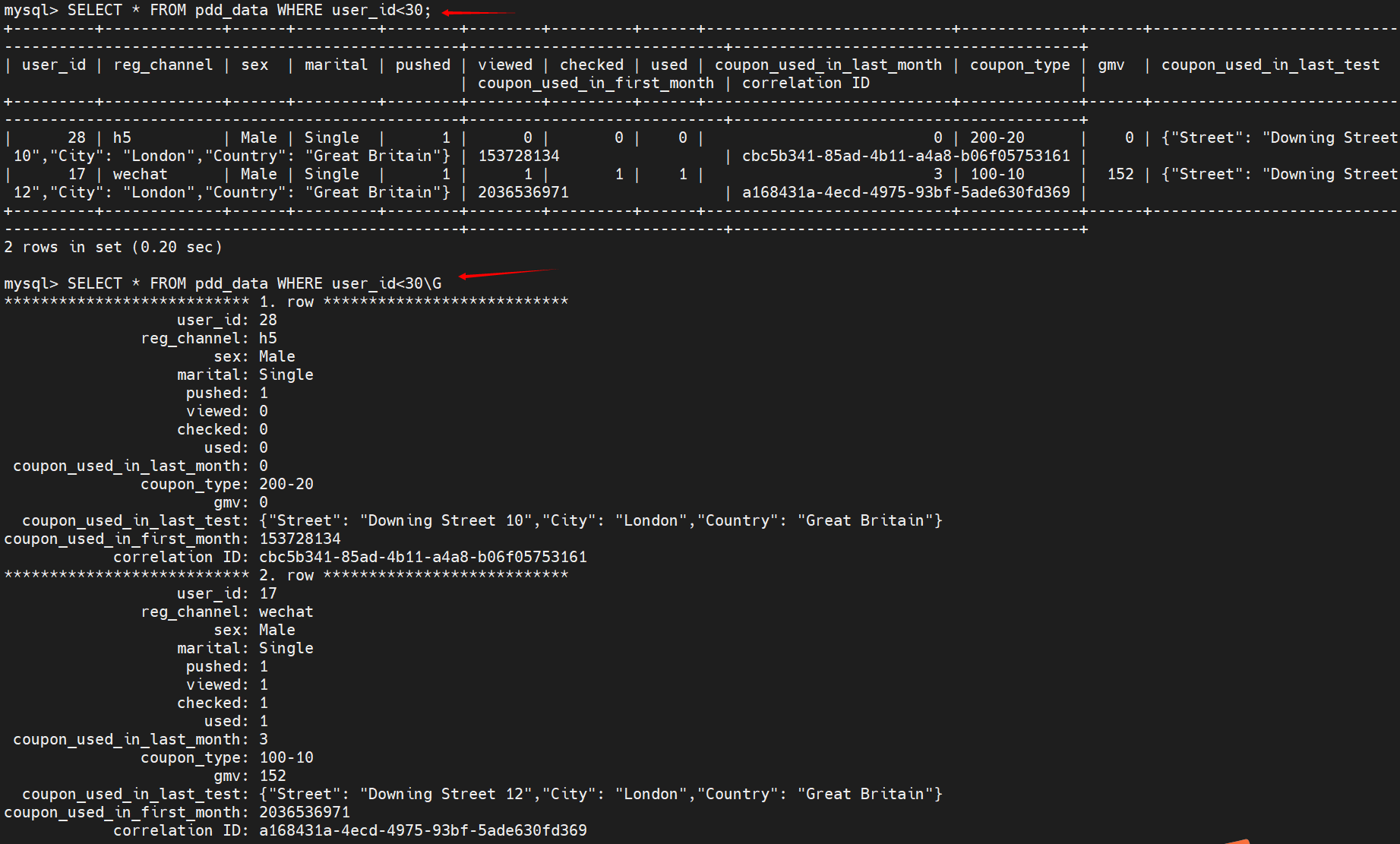
Screenshot of the experimental results :

2. Reading papers Least-Squares Fitting of Two 3-D Points Sets, Deduce and prove that the corresponding points are known ICP Solution ;
deduction :
For two sets of point clouds :

solve R and t, Minimize the following formula :

Transform the above formula :

among ,цx and цp Respectively X Point clouds and P The centroid of the point cloud .
Convert to the form of removing the center of mass :

Expand to get

Because the latter two items have
![]()
We can make the term equal to 0, Then the formula is transformed into

=0 solve t.
The above formula is further transformed into , obtain :

Measure the phase difference :

(2)

The figure on the right shows the joint probability distribution of the lidar beam model .
among ZtK Indicates the distance value returned from the measurement ,Zmax Represents the maximum value that can be measured by lidar .
It consists of four probability distributions :
Blue is the Gaussian probability distribution , Represents the actual measured distance and its uncertainty .
Green is an exponential distribution , Represents the feasibility of detecting dynamic obstacles .
Red represents random noise .
Pink represents the possibility of wrong measurement .
4. Short answer , Open answer : Design use IMU Methods of removing lidar motion distortion and answering questions .
(1) Just use IMU What are the possible disadvantages of removing motion distortion ?
(2) There is only IMU And lidar sensors , How would you design a motion distortion removal scheme ( translation + rotate ), Achieve better distortion removal effect ?
(1) deficiencies :
IMU The quadratic integration of linear acceleration may have a large error
- Design :
Within each lidar data frame , Use imu Do integral , obtain IMU Odometer .
Through time synchronization , Then determine the location of each LIDAR point beam IMU The position below the odometer coordinate system
Correct each LIDAR point beam below the starting pose of the frame .
about n Always correct the lidar data , Use icp Algorithm , take n Time and n-1 The time corrected lidar frame is matched , Get the position and attitude matched by lidar .
Use this pose to correct imu Cumulative error of , Then continue to correct the data of the next frame .
版权声明
本文为[ppipp1109]所创,转载请带上原文链接,感谢
https://yzsam.com/2022/04/202204230549076108.html
边栏推荐
- The JS timestamp of wechat applet is converted to / 1000 seconds. After six hours and one day, this Friday option calculates the time
- [appium] write scripts by designing Keyword Driven files
- 92. 反转链表 II-字节跳动高频题
- 1217_使用SCons生成目标文件
- Client example analysis of easymodbustcp
- MySQL进阶学习之SQL优化【插入,主键,排序,分组,分页,计数】
- Compare the performance of query based on the number of paging data that meet the query conditions
- flink 学习(十二)Allowed Lateness和 Side Output
- JS parsing and execution process
- 圆环回原点问题-字节跳动高频题
猜你喜欢


随机推荐
41. The first missing positive number
Add animation to the picture under V-for timing
Matlab / Simulink simulation of double closed loop DC speed regulation system
Gets the time range of the current week
[二叉数] 二叉树的最大深度+N叉树的最大深度
Read software engineering at Google (15)
[binary number] maximum depth of binary tree + maximum depth of n-ary tree
2022年流动式起重机司机国家题库模拟考试平台操作
MySQL进阶学习之SQL优化【插入,主键,排序,分组,分页,计数】
编译原理 求first集 follow集 select集预测分析表 判断符号串是否符合文法定义(有源码!!!)
剑指 Offer 03. 数组中重复的数字
Gaode map search, drag and drop query address
常用SQL语句总结
Why do some people say SCM is simple and I have to learn it so hard?
flink 学习(十二)Allowed Lateness和 Side Output
402. 移掉 K 位数字-贪心
In embedded system, must the program code in flash be moved to ram to run?
MySQL advanced index [classification, performance analysis, use, design principles]
SystemVerilog (VI) - variable
Vite configure proxy proxy to solve cross domain