当前位置:网站首页>[stc8g2k64s4] introduction of comparator and sample program of comparator power down detection
[stc8g2k64s4] introduction of comparator and sample program of comparator power down detection
2022-04-23 14:45:00 【perseverance52】
【STC8G2K64S4】 Comparator introduction and comparator power down detection example program
STC8GK2 Introduction to comparator
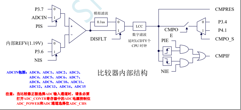
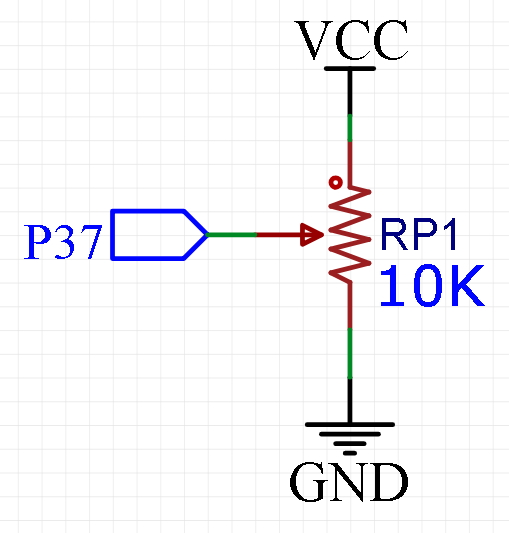
STC8G A comparator is integrated in the series MCU . The positive pole of the comparator can be P3.7 Port or ADC Analog input channel , The negative electrode can P3.6 Or internal port BandGap after OP After REFV voltage ( Internal fixed comparison voltage ). The application of multiple comparators can be realized through multiplexer and time-sharing multiplexing .
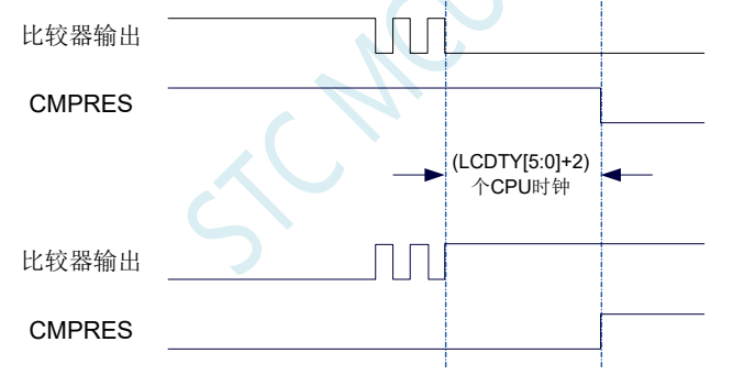
There is a programmable two-stage filter inside the comparator : Analog filtering and digital filtering . Analog filtering can filter out the burr signal in the comparison input signal , Digital filtering can wait for the input signal to be more stable before comparison . The comparison result can be obtained directly by reading the internal register bit , The result of the comparator can also be output to the external port in the forward or reverse direction . The comparison result is output to the external port, which can be used as trigger signal and feedback signal of external events , It can expand the application scope of comparison .
- Internal structure diagram of comparator
- Comparator related registers
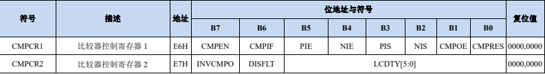
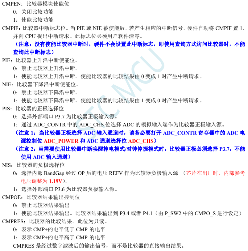
- Comparator control register 1(CMPCR1)

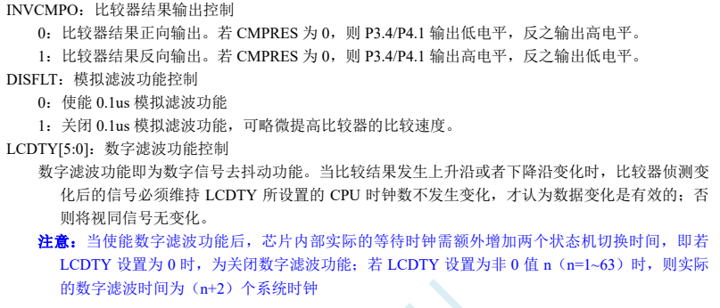
- Comparator control register 2(CMPCR2)

- Wiring instructions
Use of comparator ( Interrupt mode )
/*STC8G2 MCU interrupt mode to obtain P36 Pin voltage value and internal voltage 1.19V Compare the voltage , Output the result to P10,  When P36 Pin voltage is higher than 1.19v when , be P10 Output high level , lower than 1.19V An interrupt is triggered ,P10 Output low level */
#include "reg51.h"
#include "intrins.h"
sfr CMPCR1 = 0xe6;
sfr CMPCR2 = 0xe7;
sfr P0M1 = 0x93;
sfr P0M0 = 0x94;
sfr P1M1 = 0x91;
sfr P1M0 = 0x92;
sfr P2M1 = 0x95;
sfr P2M0 = 0x96;
sfr P3M1 = 0xb1;
sfr P3M0 = 0xb2;
sfr P4M1 = 0xb3;
sfr P4M0 = 0xb4;
sfr P5M1 = 0xc9;
sfr P5M0 = 0xca;
sbit P10 = P1^0;
sbit P11 = P1^1;

void cmp() interrupt 21 using 1
{

	CMPCR1 &= 0xbf;// Manually clear the interrupt flag ,1011,1111
	P10 = (CMPCR1 & 0x01); // Compare the result of the comparator CMPRES Output to the test port to display
}
void main()
{

    P0M0 = 0x00;// Set up a IO The port is a quasi two-way port
    P0M1 = 0x00;
    P1M0 = 0x00;
    P1M1 = 0x00;
    P2M0 = 0x00;
    P2M1 = 0x00;
    P3M0 = 0x00;
    P3M1 = 0x00;
    P4M0 = 0x00;
    P4M1 = 0x00;
    P5M0 = 0x00;
    P5M1 = 0x00;
		P10 =0;// initial P10 The port is low
    CMPCR2 = 0x00;
    CMPCR2 &= ~0x80; // Comparator forward output
// CMPCR2 |= 0x80; // Comparator reverse output
    CMPCR2 &= ~0x40; // Can make  0.1us  wave filtering
// CMPCR2 |= 0x40; // prohibit  0.1us  wave filtering
// CMPCR2 &= ~0x3f; // The result of the comparator is output directly
    CMPCR2 |= 0x10; // The comparator result passes through  16  Output after de dithering the clock
    CMPCR1 = 0x00;
    CMPCR1 |= 0x30; // Enable comparator edge interrupt
// CMPCR1 &= ~0x20; // Disable comparator rising edge interrupt
// CMPCR1 |= 0x20; // Enable the rising edge of the comparator to interrupt
// CMPCR1 &= ~0x10; // Disable the falling edge interrupt of the comparator
// CMPCR1 |= 0x10; // Enable the falling edge of the comparator to interrupt
    CMPCR1 &= ~0x08; //P3.7  by  CMP+ Input foot
// CMPCR1 |= 0x08; //ADC  Input pin is  CMP+ Input foot
		CMPCR1 &= ~0x04; // Inside  1.19V  The reference signal source is  CMP- Input foot
 // CMPCR1 |= 0x04; //P3.6  by  CMP- Input foot
// CMPCR1 &= ~0x02; // Disable comparator output
    CMPCR1 |= 0x02; // Enable comparator output
    CMPCR1 |= 0x80; // Enable comparator module
		EA =1;
    while (1)
    {

    }
}
Use of comparator ( A query )
If the query method is , Is in the while In the loop, the status of the corresponding register is continuously queried to determine the current comparator input pin (P37 mouth ) The voltage value of .
/*STC8G2 MCU interrupt mode to obtain P36 Pin voltage value and internal voltage 1.19V Compare the voltage , Output the result to P10,  When P36 Pin voltage is higher than 1.19v when , be P10 Output high level , lower than 1.19V An interrupt is triggered ,P10 Output low level */
#include "reg51.h"
#include "intrins.h"
sfr CMPCR1 = 0xe6;
sfr CMPCR2 = 0xe7;
sfr P0M1 = 0x93;
sfr P0M0 = 0x94;
sfr P1M1 = 0x91;
sfr P1M0 = 0x92;
sfr P2M1 = 0x95;
sfr P2M0 = 0x96;
sfr P3M1 = 0xb1;
sfr P3M0 = 0xb2;
sfr P4M1 = 0xb3;
sfr P4M0 = 0xb4;
sfr P5M1 = 0xc9;
sfr P5M0 = 0xca;
sbit P10 = P1^0;
sbit P11 = P1^1;

//void cmp() interrupt 21 using 1
//{

// CMPCR1 &= 0xbf;// Manually clear the interrupt flag ,1011,1111
// P10 = (CMPCR1 & 0x01); // Compare the result of the comparator CMPRES Output to the test port to display
//}
void main()
{

    P0M0 = 0x00;// Set up a IO The port is a quasi two-way port
    P0M1 = 0x00;
    P1M0 = 0x00;
    P1M1 = 0x00;
    P2M0 = 0x00;
    P2M1 = 0x00;
    P3M0 = 0x00;
    P3M1 = 0x00;
    P4M0 = 0x00;
    P4M1 = 0x00;
    P5M0 = 0x00;
    P5M1 = 0x00;
		P10 =0;// initial P10 The port is low
    CMPCR2 = 0x00;
    CMPCR2 &= ~0x80; // Comparator forward output
// CMPCR2 |= 0x80; // Comparator reverse output
    CMPCR2 &= ~0x40; // Can make  0.1us  wave filtering
// CMPCR2 |= 0x40; // prohibit  0.1us  wave filtering
// CMPCR2 &= ~0x3f; // The result of the comparator is output directly
    CMPCR2 |= 0x10; // The comparator result passes through  16  Output after de dithering the clock
    CMPCR1 = 0x00;
    CMPCR1 |= 0x30; // Enable comparator edge interrupt
// CMPCR1 &= ~0x20; // Disable comparator rising edge interrupt
// CMPCR1 |= 0x20; // Enable the rising edge of the comparator to interrupt
// CMPCR1 &= ~0x10; // Disable the falling edge interrupt of the comparator
// CMPCR1 |= 0x10; // Enable the falling edge of the comparator to interrupt
    CMPCR1 &= ~0x08; //P3.7  by  CMP+ Input foot
// CMPCR1 |= 0x08; //ADC  Input pin is  CMP+ Input foot
		CMPCR1 &= ~0x04; // Inside  1.19V  The reference signal source is  CMP- Input foot
 // CMPCR1 |= 0x04; //P3.6  by  CMP- Input foot
// CMPCR1 &= ~0x02; // Disable comparator output
    CMPCR1 |= 0x02; // Enable comparator output
    CMPCR1 |= 0x80; // Enable comparator module
// EA =1;
    while (1)
    {


// CMPCR1 &= 0xbf;// Manually clear the interrupt flag ,1011,1111
	P10= (CMPCR1 & 0x01); // Compare the result of the comparator CMPRES Output to the test port to display
    }
}
As a power down detection , It is best to use interrupt mode , To deal with Events , take P37 As an external voltage detection port , If the internal voltage is used for comparison , Namely 1.19V As a comparative value . It is recommended to use P36 As CMP- Input foot , Receive 3.3V On voltage , Single chip microcomputer adopts 5V Power supply ,P37 Pin detection 5V Voltage value , When the detection voltage is lower than 3.3V when , The interrupt will be triggered , It is equivalent to increasing the reference voltage of the comparison to 3.3V, The implementation related code is as follows :CMPCR1 |= 0x04; //P3.6 by CMP- Input foot
- P36 As CMP- Enter the pin code
/*STC8G2 MCU interrupt mode to obtain P36 Pin voltage value and internal voltage 1.19V Compare the voltage , Output the result to P10,  When P36 Pin voltage is higher than 1.19v when , be P10 Output high level , lower than 1.19V An interrupt is triggered ,P10 Output low level */
#include "reg51.h"
#include "intrins.h"
sfr CMPCR1 = 0xe6;
sfr CMPCR2 = 0xe7;
sfr P0M1 = 0x93;
sfr P0M0 = 0x94;
sfr P1M1 = 0x91;
sfr P1M0 = 0x92;
sfr P2M1 = 0x95;
sfr P2M0 = 0x96;
sfr P3M1 = 0xb1;
sfr P3M0 = 0xb2;
sfr P4M1 = 0xb3;
sfr P4M0 = 0xb4;
sfr P5M1 = 0xc9;
sfr P5M0 = 0xca;
sbit P10 = P1^0;
sbit P11 = P1^1;

void cmp() interrupt 21 using 1
{

	CMPCR1 &= 0xbf;// Manually clear the interrupt flag ,1011,1111
	P10 = (CMPCR1 & 0x01); // Compare the result of the comparator CMPRES Output to the test port to display
}
void main()
{

    P0M0 = 0x00;// Set up a IO The port is a quasi two-way port
    P0M1 = 0x00;
    P1M0 = 0x00;
    P1M1 = 0x00;
    P2M0 = 0x00;
    P2M1 = 0x00;
    P3M0 = 0x00;
    P3M1 = 0x00;
    P4M0 = 0x00;
    P4M1 = 0x00;
    P5M0 = 0x00;
    P5M1 = 0x00;
		P10 =0;// initial P10 The port is low
    CMPCR2 = 0x00;
    CMPCR2 &= ~0x80; // Comparator forward output
// CMPCR2 |= 0x80; // Comparator reverse output
    CMPCR2 &= ~0x40; // Can make  0.1us  wave filtering
// CMPCR2 |= 0x40; // prohibit  0.1us  wave filtering
// CMPCR2 &= ~0x3f; // The result of the comparator is output directly
    CMPCR2 |= 0x10; // The comparator result passes through  16  Output after de dithering the clock
    CMPCR1 = 0x00;
    CMPCR1 |= 0x30; // Enable comparator edge interrupt
// CMPCR1 &= ~0x20; // Disable comparator rising edge interrupt
// CMPCR1 |= 0x20; // Enable the rising edge of the comparator to interrupt
// CMPCR1 &= ~0x10; // Disable the falling edge interrupt of the comparator
// CMPCR1 |= 0x10; // Enable the falling edge of the comparator to interrupt
    CMPCR1 &= ~0x08; //P3.7  by  CMP+ Input foot
// CMPCR1 |= 0x08; //ADC  Input pin is  CMP+ Input foot
// CMPCR1 &= ~0x04; // Inside  1.19V  The reference signal source is  CMP- Input foot
   CMPCR1 |= 0x04; //P3.6  by  CMP- Input foot
// CMPCR1 &= ~0x02; // Disable comparator output
    CMPCR1 |= 0x02; // Enable comparator output
    CMPCR1 |= 0x80; // Enable comparator module
		EA =1;
    while (1)
    {

// P10= (CMPCR1 & 0x01); // Compare the result of the comparator CMPRES Output to the test port to display
    }
}
版权声明
本文为[perseverance52]所创,转载请带上原文链接,感谢
https://yzsam.com/2022/04/202204231426130235.html
边栏推荐
- AT89C52 MCU frequency meter (1Hz ~ 20MHz) design, LCD1602 display, including simulation, schematic diagram, PCB and code, etc
- 【无标题】
- AT89C51 MCU digital voltmeter development, measuring range 0 ~ 5V, proteus simulation, schematic diagram, PCB and C program, etc
- Upgrade of openssh and modification of version number
- 四层和八层电梯控制系统Proteus仿真设计,51单片机,附仿真和Keil C代码
- MySQL error packet out of order
- async void 导致程序崩溃
- [untitled]
- Chapter 7 of JVM series -- bytecode execution engine
- LM317的直流可调稳压电源Multisim仿真设计(附仿真+论文+参考资料)
猜你喜欢

51 MCU + LCD12864 LCD Tetris game, proteus simulation, ad schematic diagram, code, thesis, etc

ArrayList collection basic usage

QT interface optimization: QT border removal and form rounding
金九银十,入职字节跳动那一天,我哭了(蘑菇街被裁,奋战7个月拿下offer)
你还不知道责任链模式的使用场景吗?
外包干了四年,废了...
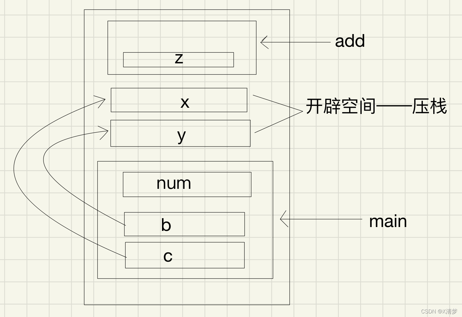
Parameter stack pressing problem of C language in structure parameter transmission
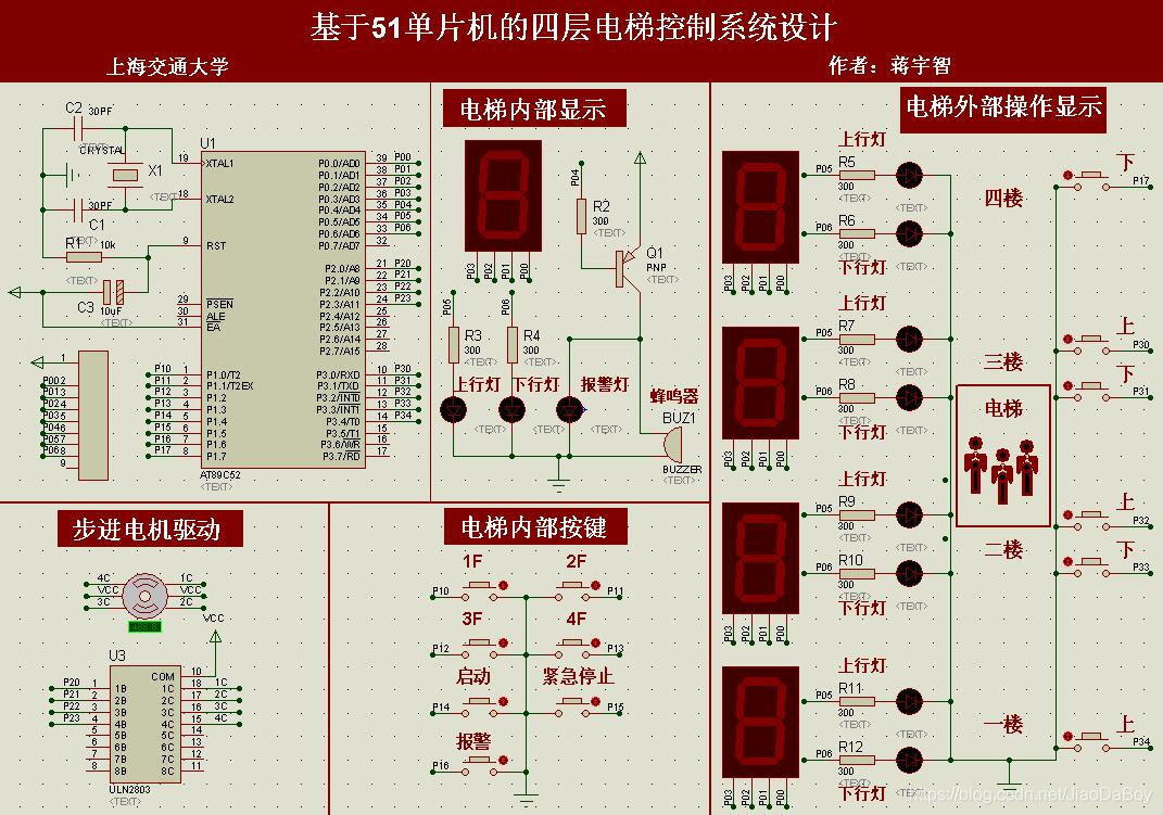
Proteus simulation design of four storey and eight storey elevator control system, 51 single chip microcomputer, with simulation and keil c code

A blog allows you to learn how to write markdown on vscode
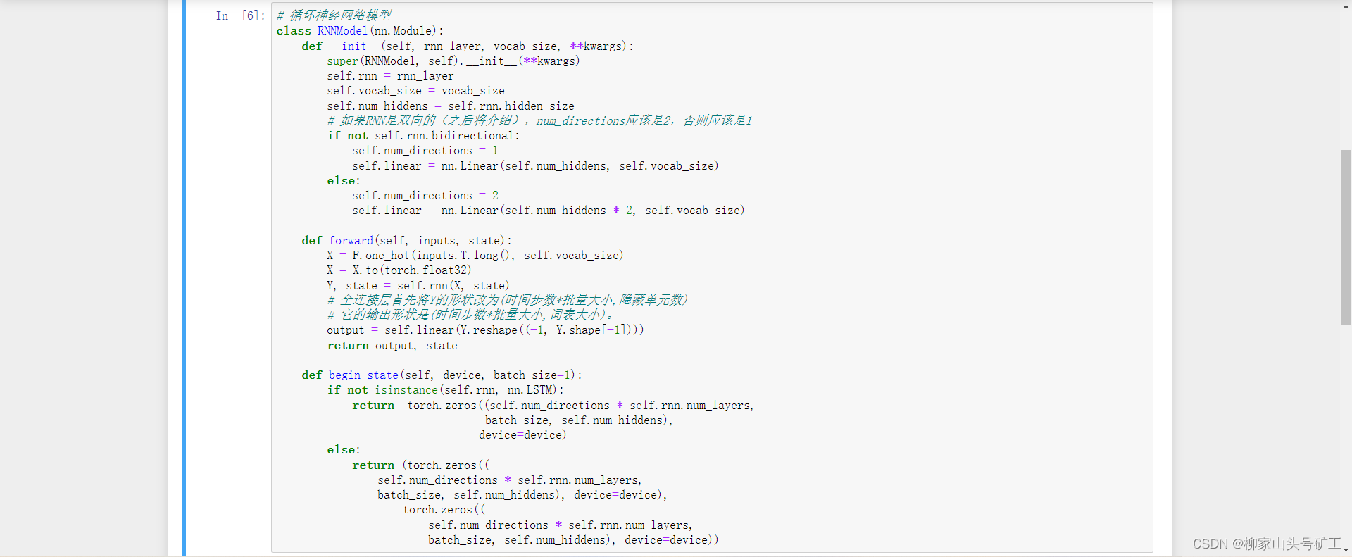
8.5 循环神经网络简洁实现
随机推荐
在游戏世界组建一支AI团队,超参数的多智能体「大乱斗」开赛
DVWA之暴力破解(Brute Force)Low-->high
QT interface optimization: QT border removal and form rounding
LotusDB 设计与实现—1 基本概念
qt之.pro文件详解
Ali developed three sides, and the interviewer's set of combined punches made me confused on the spot
Use of ansible and common modules
Find daffodils - for loop practice
电容
Model location setting in GIS data processing -cesium
Branch statement of process control
Detailed explanation of C language P2 selection branch statement
面试官:说一下类加载的过程以及类加载的机制(双亲委派机制)
QT interface optimization: double click effect
Detailed explanation of SAR command
压缩映射定理
vscode中文插件不生效问题解决
OpenFaaS实战之四:模板操作(template)
Select receives both normal data and out of band data
PCIe X1 插槽的主要用途是什么?