当前位置:网站首页>【STC8G2K64S4】比较器介绍以及比较器掉电检测示例程序
【STC8G2K64S4】比较器介绍以及比较器掉电检测示例程序
2022-04-23 14:26:00 【perseverance52】
【STC8G2K64S4】比较器介绍以及比较器掉电检测示例程序
STC8GK2比较器简介
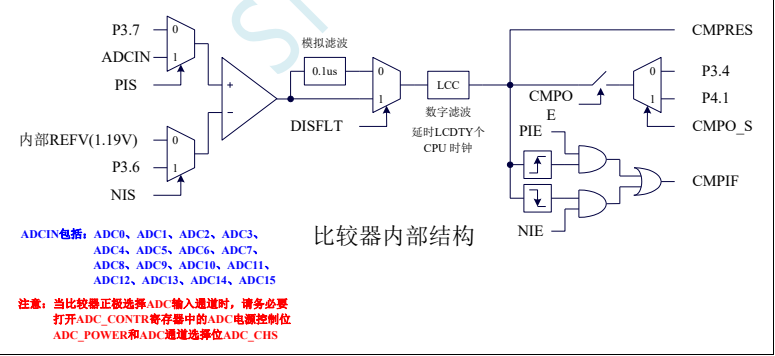
STC8G 系列单片机内部集成了一个比较器。比较器的正极可以是 P3.7 端口或者 ADC 的模拟输入通道,而负极可以 P3.6 端口或者是内部 BandGap 经过 OP 后的 REFV 电压(内部固定比较电压)。通过多路选择器和分时复用可实现多个比较器的应用.
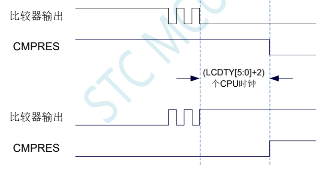
比较器内部有可程序控制的两级滤波:模拟滤波和数字滤波。模拟滤波可以过滤掉比较输入信号中的毛刺信号,数字滤波可以等待输入信号更加稳定后再进行比较。比较结果可直接通过读取内部寄存器位获得,也可将比较器结果正向或反向输出到外部端口。将比较结果输出到外部端口可用作外部事件的触发信号和反馈信号,可扩大比较的应用范围。
- 比较器内部结构图
- 比较器相关的寄存器
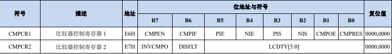
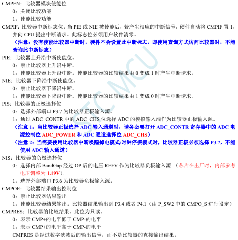
- 比较器控制寄存器 1(CMPCR1)

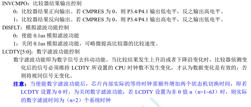
- 比较器控制寄存器 2(CMPCR2)

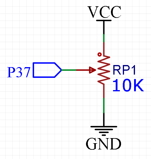
- 接线说明
比较器的使用(中断方式)
/*STC8G2单片机中断方式获取P36引脚电压值与内部1.19V电压进行比较,将结果输出到P10, 当P36引脚电压高于1.19v时,则P10输出高电平,低于1.19V则触发中断,P10输出低电平*/
#include "reg51.h"
#include "intrins.h"
sfr CMPCR1 = 0xe6;
sfr CMPCR2 = 0xe7;
sfr P0M1 = 0x93;
sfr P0M0 = 0x94;
sfr P1M1 = 0x91;
sfr P1M0 = 0x92;
sfr P2M1 = 0x95;
sfr P2M0 = 0x96;
sfr P3M1 = 0xb1;
sfr P3M0 = 0xb2;
sfr P4M1 = 0xb3;
sfr P4M0 = 0xb4;
sfr P5M1 = 0xc9;
sfr P5M0 = 0xca;
sbit P10 = P1^0;
sbit P11 = P1^1;

void cmp() interrupt 21 using 1
{

	CMPCR1 &= 0xbf;//手动清除清除中断标志,1011,1111
	P10 = (CMPCR1 & 0x01); //将比较器结果CMPRES输出到测试口显示
}
void main()
{

    P0M0 = 0x00;//设置个IO端口为准双向口
    P0M1 = 0x00;
    P1M0 = 0x00;
    P1M1 = 0x00;
    P2M0 = 0x00;
    P2M1 = 0x00;
    P3M0 = 0x00;
    P3M1 = 0x00;
    P4M0 = 0x00;
    P4M1 = 0x00;
    P5M0 = 0x00;
    P5M1 = 0x00;
		P10 =0;//初始P10端口为低电平
    CMPCR2 = 0x00;
    CMPCR2 &= ~0x80; //比较器正向输出
// CMPCR2 |= 0x80; //比较器反向输出
    CMPCR2 &= ~0x40; //使能 0.1us 滤波
// CMPCR2 |= 0x40; //禁止 0.1us 滤波
// CMPCR2 &= ~0x3f; //比较器结果直接输出
    CMPCR2 |= 0x10; //比较器结果经过 16 个去抖时钟后输出
    CMPCR1 = 0x00;
    CMPCR1 |= 0x30; //使能比较器边沿中断
// CMPCR1 &= ~0x20; //禁止比较器上升沿中断
// CMPCR1 |= 0x20; //使能比较器上升沿中断
// CMPCR1 &= ~0x10; //禁止比较器下降沿中断
// CMPCR1 |= 0x10; //使能比较器下降沿中断
    CMPCR1 &= ~0x08; //P3.7 为 CMP+输入脚
// CMPCR1 |= 0x08; //ADC 输入脚为 CMP+输入脚
		CMPCR1 &= ~0x04; //内部 1.19V 参考信号源为 CMP-输入脚
 // CMPCR1 |= 0x04; //P3.6 为 CMP-输入脚
// CMPCR1 &= ~0x02; //禁止比较器输出
    CMPCR1 |= 0x02; //使能比较器输出
    CMPCR1 |= 0x80; //使能比较器模块
		EA =1;
    while (1)
    {

    }
}
比较器的使用(查询方式)
查询方式的话,就是在while循环里面不断查询对应寄存器的状态来确定当前比较器输入引脚(P37口)的电压值。
/*STC8G2单片机中断方式获取P36引脚电压值与内部1.19V电压进行比较,将结果输出到P10, 当P36引脚电压高于1.19v时,则P10输出高电平,低于1.19V则触发中断,P10输出低电平*/
#include "reg51.h"
#include "intrins.h"
sfr CMPCR1 = 0xe6;
sfr CMPCR2 = 0xe7;
sfr P0M1 = 0x93;
sfr P0M0 = 0x94;
sfr P1M1 = 0x91;
sfr P1M0 = 0x92;
sfr P2M1 = 0x95;
sfr P2M0 = 0x96;
sfr P3M1 = 0xb1;
sfr P3M0 = 0xb2;
sfr P4M1 = 0xb3;
sfr P4M0 = 0xb4;
sfr P5M1 = 0xc9;
sfr P5M0 = 0xca;
sbit P10 = P1^0;
sbit P11 = P1^1;

//void cmp() interrupt 21 using 1
//{

// CMPCR1 &= 0xbf;//手动清除清除中断标志,1011,1111
// P10 = (CMPCR1 & 0x01); //将比较器结果CMPRES输出到测试口显示
//}
void main()
{

    P0M0 = 0x00;//设置个IO端口为准双向口
    P0M1 = 0x00;
    P1M0 = 0x00;
    P1M1 = 0x00;
    P2M0 = 0x00;
    P2M1 = 0x00;
    P3M0 = 0x00;
    P3M1 = 0x00;
    P4M0 = 0x00;
    P4M1 = 0x00;
    P5M0 = 0x00;
    P5M1 = 0x00;
		P10 =0;//初始P10端口为低电平
    CMPCR2 = 0x00;
    CMPCR2 &= ~0x80; //比较器正向输出
// CMPCR2 |= 0x80; //比较器反向输出
    CMPCR2 &= ~0x40; //使能 0.1us 滤波
// CMPCR2 |= 0x40; //禁止 0.1us 滤波
// CMPCR2 &= ~0x3f; //比较器结果直接输出
    CMPCR2 |= 0x10; //比较器结果经过 16 个去抖时钟后输出
    CMPCR1 = 0x00;
    CMPCR1 |= 0x30; //使能比较器边沿中断
// CMPCR1 &= ~0x20; //禁止比较器上升沿中断
// CMPCR1 |= 0x20; //使能比较器上升沿中断
// CMPCR1 &= ~0x10; //禁止比较器下降沿中断
// CMPCR1 |= 0x10; //使能比较器下降沿中断
    CMPCR1 &= ~0x08; //P3.7 为 CMP+输入脚
// CMPCR1 |= 0x08; //ADC 输入脚为 CMP+输入脚
		CMPCR1 &= ~0x04; //内部 1.19V 参考信号源为 CMP-输入脚
 // CMPCR1 |= 0x04; //P3.6 为 CMP-输入脚
// CMPCR1 &= ~0x02; //禁止比较器输出
    CMPCR1 |= 0x02; //使能比较器输出
    CMPCR1 |= 0x80; //使能比较器模块
// EA =1;
    while (1)
    {


// CMPCR1 &= 0xbf;//手动清除清除中断标志,1011,1111
	P10= (CMPCR1 & 0x01); //将比较器结果CMPRES输出到测试口显示
    }
}
作为掉电检测的话,最好使用中断方式,来处理事件,将P37作为外部电压检测口,如果使用内部电压进行比较的话,就是1.19V作为比较值。建议使用P36作为CMP-输入脚,接到3.3V电压上,单片机采用5V供电,P37引脚检测5V电压值,当检测电压低于3.3V时,就会触发中断,相当于将比较的基准电压提高到了3.3V,实现相关代码如下:CMPCR1 |= 0x04; //P3.6 为 CMP-输入脚
- P36 作为CMP-输入脚代码
/*STC8G2单片机中断方式获取P36引脚电压值与内部1.19V电压进行比较,将结果输出到P10, 当P36引脚电压高于1.19v时,则P10输出高电平,低于1.19V则触发中断,P10输出低电平*/
#include "reg51.h"
#include "intrins.h"
sfr CMPCR1 = 0xe6;
sfr CMPCR2 = 0xe7;
sfr P0M1 = 0x93;
sfr P0M0 = 0x94;
sfr P1M1 = 0x91;
sfr P1M0 = 0x92;
sfr P2M1 = 0x95;
sfr P2M0 = 0x96;
sfr P3M1 = 0xb1;
sfr P3M0 = 0xb2;
sfr P4M1 = 0xb3;
sfr P4M0 = 0xb4;
sfr P5M1 = 0xc9;
sfr P5M0 = 0xca;
sbit P10 = P1^0;
sbit P11 = P1^1;

void cmp() interrupt 21 using 1
{

	CMPCR1 &= 0xbf;//手动清除清除中断标志,1011,1111
	P10 = (CMPCR1 & 0x01); //将比较器结果CMPRES输出到测试口显示
}
void main()
{

    P0M0 = 0x00;//设置个IO端口为准双向口
    P0M1 = 0x00;
    P1M0 = 0x00;
    P1M1 = 0x00;
    P2M0 = 0x00;
    P2M1 = 0x00;
    P3M0 = 0x00;
    P3M1 = 0x00;
    P4M0 = 0x00;
    P4M1 = 0x00;
    P5M0 = 0x00;
    P5M1 = 0x00;
		P10 =0;//初始P10端口为低电平
    CMPCR2 = 0x00;
    CMPCR2 &= ~0x80; //比较器正向输出
// CMPCR2 |= 0x80; //比较器反向输出
    CMPCR2 &= ~0x40; //使能 0.1us 滤波
// CMPCR2 |= 0x40; //禁止 0.1us 滤波
// CMPCR2 &= ~0x3f; //比较器结果直接输出
    CMPCR2 |= 0x10; //比较器结果经过 16 个去抖时钟后输出
    CMPCR1 = 0x00;
    CMPCR1 |= 0x30; //使能比较器边沿中断
// CMPCR1 &= ~0x20; //禁止比较器上升沿中断
// CMPCR1 |= 0x20; //使能比较器上升沿中断
// CMPCR1 &= ~0x10; //禁止比较器下降沿中断
// CMPCR1 |= 0x10; //使能比较器下降沿中断
    CMPCR1 &= ~0x08; //P3.7 为 CMP+输入脚
// CMPCR1 |= 0x08; //ADC 输入脚为 CMP+输入脚
// CMPCR1 &= ~0x04; //内部 1.19V 参考信号源为 CMP-输入脚
   CMPCR1 |= 0x04; //P3.6 为 CMP-输入脚
// CMPCR1 &= ~0x02; //禁止比较器输出
    CMPCR1 |= 0x02; //使能比较器输出
    CMPCR1 |= 0x80; //使能比较器模块
		EA =1;
    while (1)
    {

// P10= (CMPCR1 & 0x01); //将比较器结果CMPRES输出到测试口显示
    }
}
版权声明
本文为[perseverance52]所创,转载请带上原文链接,感谢
https://blog.csdn.net/weixin_42880082/article/details/124360835
边栏推荐
- TUN 设备原理
- Redis源码分析之PSYNC同步
- 阿里研发三面,面试官一套组合拳让我当场懵逼
- Proteus simulation design of DC adjustable regulated power supply (with simulation + paper and other data)
- kprobe 的 3 种使用
- 1 minute to understand the execution process and permanently master the for cycle (with for cycle cases)
- 51单片机+LCD12864液晶显示的俄罗斯方块游戏,Proteus仿真、AD原理图、代码、论文等
- 顺序栈的基本操作
- 金九银十,入职字节跳动那一天,我哭了(蘑菇街被裁,奋战7个月拿下offer)
- 1分钟看懂执行流程,永久掌握for循环(附for循环案例)
猜你喜欢
外包干了四年,废了...
ASEMI超快恢复二极管与肖特基二极管可以互换吗
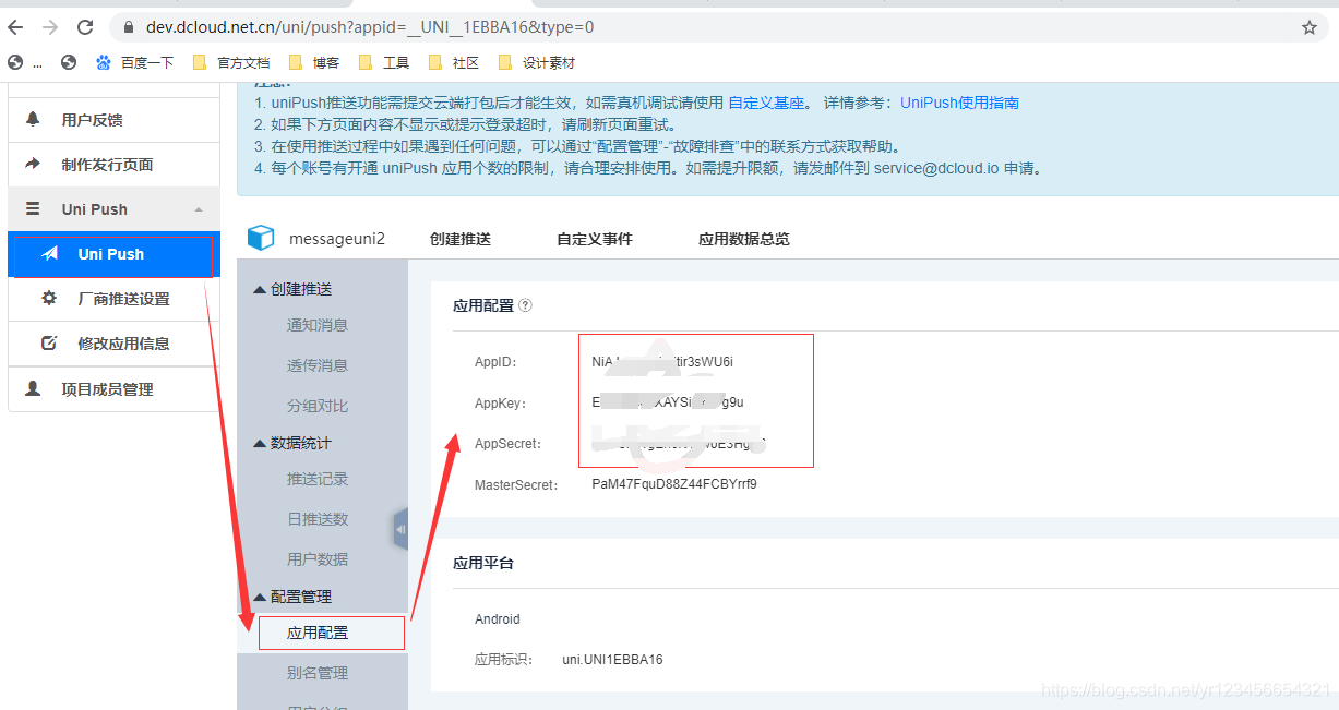
Uni app message push

QT actual combat: Yunxi chat room
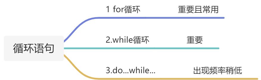
1 minute to understand the execution process and permanently master the for cycle (with for cycle cases)
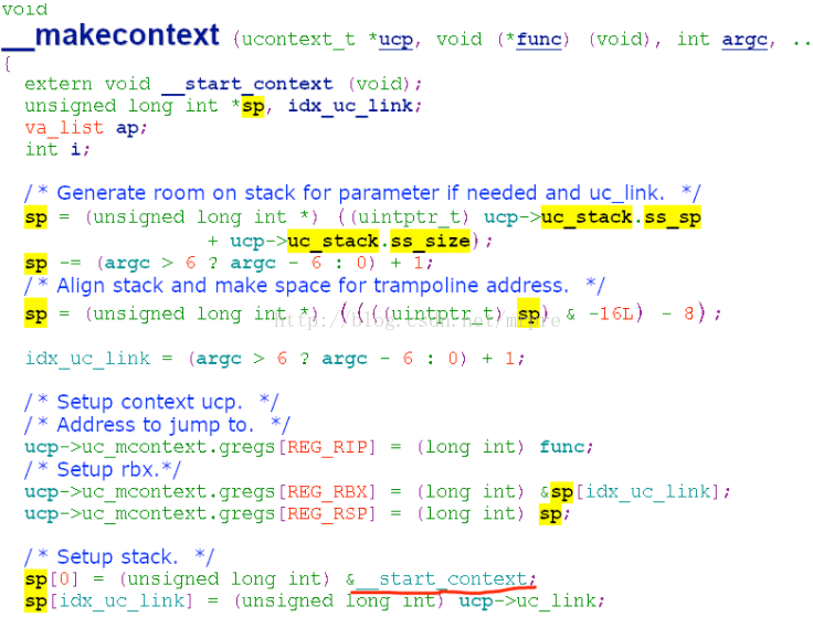
setcontext getcontext makecontext swapcontext
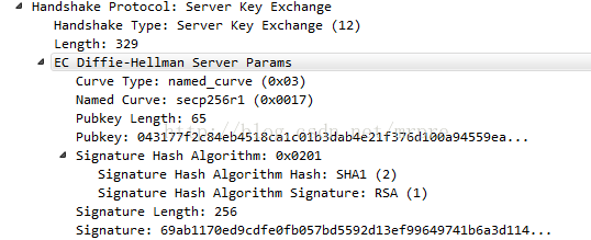
TLS/SSL 协议详解 (28) TLS 1.0、TLS 1.1、TLS 1.2之间的区别
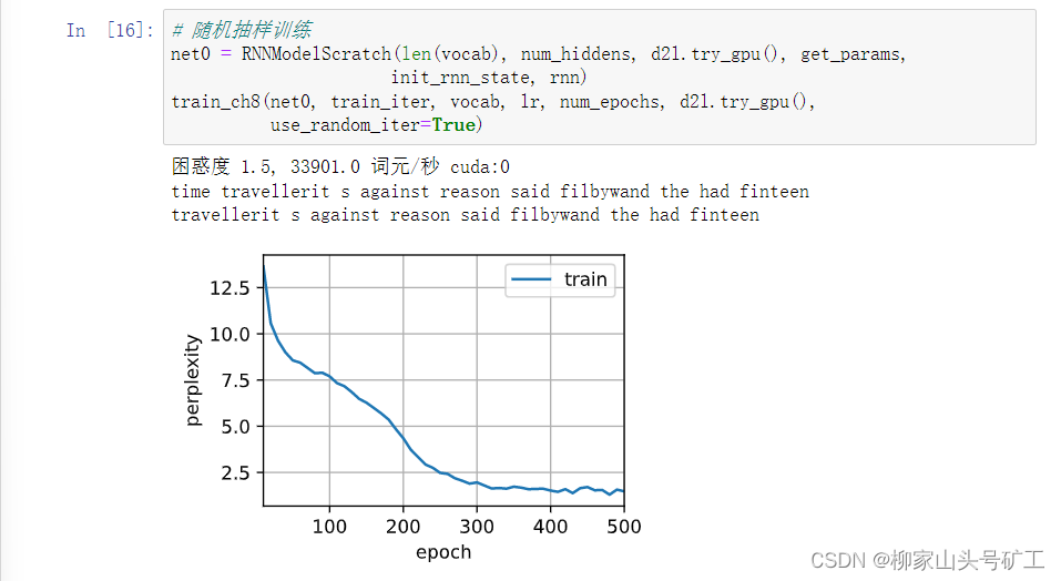
8.4 循环神经网络从零实现
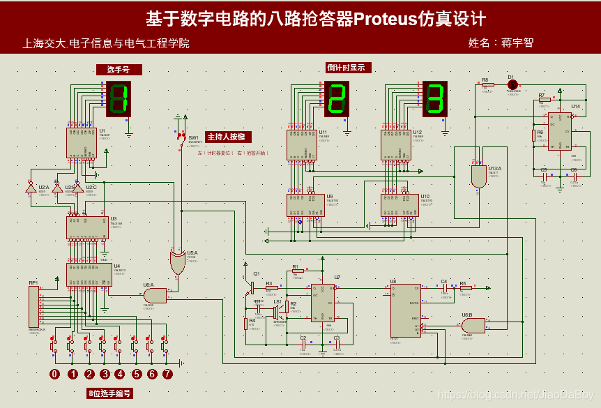
555定时器+74系列芯片搭建八路抢答器,30s倒计时,附Proteus仿真等
I thought I could lie down and enter Huawei, but I was confused when I received JD / didi / iqiyi offers one after another
随机推荐
外包干了四年,废了...
Nacos作为配置中心(四) 使用Demo
tcp_diag 内核相关实现 1 调用层次
Redis源码分析之HSET流程与ziplist
顺序栈的基本操作
Tongxin UOS php7 2.3 upgrade to php7.0 two point two four
LLVM - 生成加法
AT89C51单片机的数字电压表开发,量程0~5V,proteus仿真,原理图PCB和C程序等
八路抢答器系统51单片机设计【附Proteus仿真、C程序、原理图及PCB文件、元器件清单和论文等】
Ali developed three sides, and the interviewer's set of combined punches made me confused on the spot
一篇博客让你学会在vscode上编写markdown
Detailed explanation of C language P2 selection branch statement
循环队列的基本操作(实验)
Solve the problem of SSH configuration file optimization and slow connection
8.3 语言模型与数据集
QT interface optimization: double click effect
C语言p2选择分支语句详解
JS progress bar, displaying the loading progress
ArrayList collection basic usage
asp.net使用MailMessage发送邮件的方法