当前位置:网站首页>CANopen STM32 transplantation
CANopen STM32 transplantation
2022-04-23 18:22:00 【Things will turn when they reach the extreme 1024】
The source code is attached at the end of the article 、 Marked data 、 The transplanted program and the source code required for transplantation
https://download.csdn.net/download/qq_27620407/12938986
link :https://pan.baidu.com/s/1By-HiY4xopeGk7a1yi-p8w
Extraction code :rkd8
1、 transplant
Step one : Create a new folder in the new project directory CanFestival, And then CanFestival I'm gonna go ahead and create a new folder driver、inc and src, And then inc New under the folder stm32 Folder
Step two :
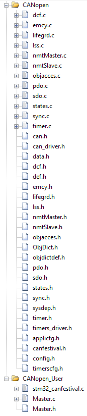
take CanFestival-3-10\src In the catalog dcf.c、emcy.c、lifegrd.c、lss.c、nmtMaster.c、nmtSlave.c、objacces.c、pdo.c、sdo.c、states.c、sync.c、timer.c common 12 Copy files to CanFestival\src Under the table of contents ;symbols.c Don't
take CanFestival-3-10\include All under directory .h Documents in total 19 Copy all files to CanFestival\inc Under the table of contents ,
And then CanFestival-3-10\examples\AVR\Slave In the catalog ObjDict.h Copy the file , altogether 20 individual .h file ;
take CanFestival-3-10\include\AVR In the catalog applicfg.h、canfestival.h、config.h、timerscfg.h common 4 Copy header files to canfestival\inc\stm32 Under the table of contents ;
Finally, the object dictionary TestSlave.c、TestSlave.h、TestMaster.h、TestMaster.c copy to canfestival\driver Under the table of contents , And create a new one in this directory stm32_canfestival.c file . These four files are object dictionaries , This is hard to find in the official library , Some routines have only .h Of documents , When transplanting, first use the dictionary generation tool to generate a blank ,TestMaster Is the name of the host ,TestSlave Is the name of the slave .
Step three :
take CanFestival\src All under directory .c File added to project ;
take canfestival\driver In the catalog stm32_canfestival.c File added to project ;
If you implement a slave device , then canfestival\driver In the catalog TestSlave.c File added to project ,
If the main device is implemented , Will TestMaster.c File added to project ;
Step four : Put the file directory canfestival\inc、canfestival\inc\stm32、canfestival\driver Wait for the path to be added to the project, including the path .
Step five : stay stm32_canfestival.c Include header file #include “canfestival.h”, And define the following functions :
void setTimer(TIMEVAL value)
{
}
TIMEVAL getElapsedTime(void)
{
return 1;
}
unsigned char canSend(CAN_PORT notused, Message *m)
{
return 1;
}
You can define an empty function first , Wait until the compilation passes , Add content to it , These functions are defined for reference canfestival The source code calls , If these functions cannot be found, the compilation will report an error .
File directory :
Step six : Go through the steps above , All the papers are in order , But there must be errors in compilation , Comment or delete config.h The following lines in the file can be compiled through :
#include <inttypes.h>
#include <avr\io.h>
#include <avr\interrupt.h>
#include <avr/pgmspace.h>
#include <avr\sleep.h>
#include <avr\wdt.h>
Step seven : After solving all the compilation errors , Next, implement the just defined 3 An empty function ,
function void setTimer(TIMEVAL value) Mainly used by the source code for timing , When the time comes, you need to call the function TimeDispatch(),
function TIMEVAL getElapsedTime(void) It is mainly used by the source code to query how much time is left before the next timing trigger ,
unsigned char canSend(CAN_PORT notused, Message *m) Function is mainly used by the source code to send a CAN Bag , You need to call the driver to put a CAN Send out the bag .
Step eight :timerscfg.h file
#define MS_TO_TIMEVAL(ms) ((ms) * 1)
#define US_TO_TIMEVAL(us) ((us)/1)
This involves CANopen Unit time of , Must match !!!!1ms Timer interrupt uses this parameter
We are stm32_canfestival.c Several variables defined in the file are as follows :
unsigned int TimeCNT=0;// Time count
unsigned int NextTime=0;// Next trigger time count
unsigned int TIMER_MAX_COUNT=70000;// Maximum time count
static TIMEVAL last_time_set = TIMEVAL_MAX;// Last time count
setTimer and getElapsedTime The function is implemented as follows :
//Set the next alarm //
void setTimer(TIMEVAL value)
{

        NextTime=(TimeCNT+value)%TIMER_MAX_COUNT;
}

// Get the elapsed time since the last occured alarm //
TIMEVAL getElapsedTime(void)
{

        int ret=0;
        ret = TimeCNT> last_time_set ? TimeCNT - last_time_set : TimeCNT + TIMER_MAX_COUNT - last_time_set;
        //last_time_set = TimeCNT;
        return ret;
}
In addition, there will be a 1 Millisecond timer , Every time 1 Call the following function in milliseconds . This function is in 1ms Timer interrupt service function
void timerForCan(void)
{

        TimeCNT++;
        if (TimeCNT>=TIMER_MAX_COUNT)
        {

                TimeCNT=0;
        }
        if (TimeCNT==NextTime)
        {

                TimeDispatch();
        }
}

void TIM7_IRQHandler(void)
{

	if(TIM7->SR&0X0001)// interrupt
	{


	}
	TIM7->SR&=~(1<<0);// Clears the interrupt flag bit
	last_time_set = TimeCNT;
	timerForCan();
}
Last
// Slave
#include "TestSlave.h"
unsigned char nodeID=0x21;
extern CO_Data TestSlave_Data;
// Calling function ( such as main function ) Call the following code to initialize
setNodeId(&TestSlave_Data, nodeID);
setState(&TestSlave_Data, Initialisation);        // Init the state
 among TestSlave_Data stay TestSlave.c In the definition of
// host
#include "TestMaster.h"
unsigned char nodeID=0x21;
extern CO_Data TestMaster_Data;
// Calling function ( such as main function ) Call the following code to initialize
setNodeId(&TestMaster_Data, nodeID);
setState(&TestMaster_Data, Initialisation);        // Init the state
 among TestMaster_Data stay TestMaster.c In the definition of
Then start calling TimerForCan() Of 1 Millisecond timer , Receiving CAN Call the source function from the data canDispatch(&TestSlave_Data, &m);
canfestival The source code can run , If it is necessary to conduct joint commissioning with the main equipment , We need to achieve canSend function , This is related to the platform Can Drive related .
2、STM32 Timers and CAN Transceiver function
STM32 aspect , Rewrite sending and receiving according to your own program needs .
Receive interrupt , After reading out the information, you need to call void canDispatch(CO_Data* d, Message *m)
/*CAN Interrupt service function */
void USB_LP_CAN1_RX0_IRQHandler(void)
{

	Message m;
	u8 *ide;
	CAN_Rx2_Msg(0,&m.cob_id,ide,&m.rtr,&m.len,m.data);// receive data
	canDispatch(&TestMaster_Data, &m);
}
/* Receive data structure */
typedef struct {

  UNS16 cob_id;
  UNS8 rtr;
  UNS8 len;
  UNS8 data[8];
} Message;
/* Receive data function */
//fifox: Mail box number
//id: standard ID(11 position )/ Expand ID(11 position +18 position )
//ide:0, Standard frame ;1, Extended frames
//rtr:0, Data frame ;1, Remote frame
//len: Received data length ( Fixed for 8 Bytes , In time triggered mode , The valid data are 6 Bytes )
//dat: Data cache
void CAN_Rx2_Msg(u8 fifox,u16 *id,u8 *ide,u8 *rtr,u8 *len,UNS8 dat[8])
{

	*ide=CAN1->sFIFOMailBox[fifox].RIR&0x04;	// Get the value of the identifier selection bit
 	if(*ide==0)// Standard Identifier
	{

		*id=CAN1->sFIFOMailBox[fifox].RIR>>21;
	}else	   // Extension identifier
	{

		*id=CAN1->sFIFOMailBox[fifox].RIR>>3;
	}
	*rtr=CAN1->sFIFOMailBox[fifox].RIR&0x02;	// Get the remote send request value .
	*len=CAN1->sFIFOMailBox[fifox].RDTR&0x0F;	// obtain DLC
 	//*fmi=(CAN1->sFIFOMailBox[FIFONumber].RDTR>>8)&0xFF;// obtain FMI
	// receive data
	dat[0]=CAN1->sFIFOMailBox[fifox].RDLR&0XFF;
	dat[1]=(CAN1->sFIFOMailBox[fifox].RDLR>>8)&0XFF;
	dat[2]=(CAN1->sFIFOMailBox[fifox].RDLR>>16)&0XFF;
	dat[3]=(CAN1->sFIFOMailBox[fifox].RDLR>>24)&0XFF;
	dat[4]=CAN1->sFIFOMailBox[fifox].RDHR&0XFF;
	dat[5]=(CAN1->sFIFOMailBox[fifox].RDHR>>8)&0XFF;
	dat[6]=(CAN1->sFIFOMailBox[fifox].RDHR>>16)&0XFF;
	dat[7]=(CAN1->sFIFOMailBox[fifox].RDHR>>24)&0XFF;
  	if(fifox==0)CAN1->RF0R|=0X20;// Release FIFO0 mailbox
	else if(fifox==1)CAN1->RF1R|=0X20;// Release FIFO1 mailbox
}
send out , Because there is no use of library functions here , It's register mode , Therefore, the receiving function cannot use simple library functions , But it's more portable .
/* Send deposit structure */
typedef struct
{

  uint32_t StdId;
  uint32_t ExtId;
  uint8_t IDE;
  uint8_t RTR;
  uint8_t DLC;
  uint8_t Data[8];
} CanTxMsg;
/* Send deposit interface */
typedef struct {

  u16 cob_id;	/**< message's ID */
  u8 rtr;		/**< remote transmission request. (0 if not rtr message, 1 if rtr message) */
  u8 len;		/**< message's length (0 to 8) */
  u8 data[8];   /**< message's datas */
} can_message_t;   //CAN Basic structure of message

#define CAN_Id_Standard ((uint32_t)0x00000000) /*!< Standard Id */

//can Send a set of data , Send in standard frame format
// Return value :0,  Send successfully ;
//  other , fail in send ;
u8 Can_Send_Msg(can_message_t *msg)
{

	u8 mbox;
	u16 i=0;
	CanTxMsg TxMessage;
	TxMessage.StdId = msg->cob_id;			//  Standard Identifier
	TxMessage.ExtId = 0;			        //  Set identifier extension
	TxMessage.IDE = CAN_Id_Standard; 	    //  Standard frame
	TxMessage.RTR = msg->rtr;		        //  Data frame
	TxMessage.DLC = msg->len;				//  The length of data to be sent
	for(i=0; i<msg->len; i++)
    {

        TxMessage.Data[i] = msg->data[i];
    }
	mbox=CAN_Tx_Msg(TxMessage.StdId,TxMessage.IDE,TxMessage.RTR,TxMessage.DLC,TxMessage.Data);		// send data
	i=0;
	while((CAN_Tx_Staus(mbox)!=0X07)&&(i<0XFFF))i++;// Wait for the end of sending
	if(i>=0XFFF)return 1;
	return 0;
}
/*Canopen Send interface */
unsigned char canSend(CAN_PORT notused, Message *m)
{

    return Can_Send_Msg((can_message_t *) m);   // send out CAN news
}
/* Sending function */
//id: standard ID(11 position )/ Expand ID(11 position +18 position )
//ide:0, Standard frame ;1, Extended frames
//rtr:0, Data frame ;1, Remote frame
//len: The length of data to be sent ( Fixed for 8 Bytes , In time triggered mode , The valid data are 6 Bytes )
//*dat: Data pointer .
// Return value :0~3, Mailbox number .0XFF, No valid mailbox .
u8 CAN_Tx_Msg(u32 id,u8 ide,u8 rtr,u8 len,u8 *dat)
{

	u8 mbox;
	if(CAN1->TSR&(1<<26))mbox=0;		// mailbox 0 It's empty
	else if(CAN1->TSR&(1<<27))mbox=1;	// mailbox 1 It's empty
	else if(CAN1->TSR&(1<<28))mbox=2;	// mailbox 2 It's empty
	else return 0XFF;					// No empty mailbox , Unable to send
	CAN1->sTxMailBox[mbox].TIR=0;		// Clear previous settings
	if(ide==0)	// Standard frame
	{

		id&=0x7ff;// Take low 11 position stdid
		id<<=21;
	}else		// Extended frames
	{

		id&=0X1FFFFFFF;// Take low 32 position extid
		id<<=3;
	}
	CAN1->sTxMailBox[mbox].TIR|=id;
	CAN1->sTxMailBox[mbox].TIR|=ide<<2;
	CAN1->sTxMailBox[mbox].TIR|=rtr<<1;
	len&=0X0F;// Get four places lower
	CAN1->sTxMailBox[mbox].TDTR&=~(0X0000000F);
	CAN1->sTxMailBox[mbox].TDTR|=len;	// Set up DLC.
	// The data to be sent is stored in the mailbox .
	CAN1->sTxMailBox[mbox].TDHR=(((u32)dat[7]<<24)|
								((u32)dat[6]<<16)|
 								((u32)dat[5]<<8)|
								((u32)dat[4]));
	CAN1->sTxMailBox[mbox].TDLR=(((u32)dat[3]<<24)|
								((u32)dat[2]<<16)|
 								((u32)dat[1]<<8)|
								((u32)dat[0]));
	CAN1->sTxMailBox[mbox].TIR|=1<<0; 	// Request to send mailbox data
	return mbox;
}
3 python And object dictionary generation tool canfestival Installation steps :
1. install python-2.6.2.msi, Directly select the default installation path , After loading, set the environment variable , If it is the default mode , The environment variable path is set to C:\Python26;( Note that environment variables are separated by semicolons ), If it's a custom path , Please change the environment variable to your custom installation path , The purpose is to enable the operating system to find python command
a. stay canfestival Enter... In the folder objdictgen Catalog
b. decompression Gnosis_Utils-current.tar.gz
c. open cmd,cd Order to enter Gnosis_Utils-1.2.2 Catalog , function python setup.py install.
2. Install again wxPython3.0-win32-3.0.0.0-py26.exe, After installation , Double click directly to run objdictgen In the directory objdictedit.py file , That's it .
SDO write in
SDO write in ( Host send )
| Number of bytes | ID | RTR | Function code | Index_L | Index_H | Sub index | data | data | data | data |
|---|---|---|---|---|---|---|---|---|---|---|
| A byte | 600 + ServNodeId | 0 | 2F | Index_L | Index_H | Sub index | D0 | - | - | - |
| Two bytes | 600 + ServNodeId | 0 | 2B | Index_L | Index_H | Sub index | D0 | D1 | - | - |
| Three bytes | 600 + ServNodeId | 0 | 27 | Index_L | Index_H | Sub index | D0 | D1 | D2 | - |
| Four bytes | 600 + ServNodeId | 0 | 23 | Index_L | Index_H | Sub index | D0 | D1 | D2 | D3 |
SDO write in ( The host receives )
success :
| ID | RTR | Function code | Index_L | Index_H | Sub index | data | data | data | data |
|---|---|---|---|---|---|---|---|---|---|
| 580 + Serv NodeId | 0 | 60 | Index_L | Index_H | Sub index | 00 | 00 | 00 | 00 |
When the failure :
| ID | RTR | Function code | Index_L | Index_H | Sub index | data[0…3] |
|---|---|---|---|---|---|---|
| 580 + Serv NodeId | 0 | 80 | Index_L | Index_H | Sub index | SDO abort code error |
example :DI:0x621 DLC 8 Standard frame Data frame DATA:2F 01 14 02 FD 00 00 00
write in ID by 0x21 Of 0x1401, Sub indicators 0x02, The data is 0xFD
success :DI:0x5A1 DLC 8 Standard frame Data frame DATA:60 01 14 02 00 00 00 00
DI:0x621 DLC 8 Standard frame Data frame DATA:23 01 16 02 FD 65 43 21
write in ID by 0x21 Of 0x1601, Sub indicators 0x02, The data is 0x314365FD
SDO Read
SDO Read ( Host send )
| ID | RTR | Function code | Index_L | Index_H | Sub index | data | data | data | data |
|---|---|---|---|---|---|---|---|---|---|
| 600 + Serv NodeId | 0 | 40 | Index_L | Index_H | Sub index | 00 | 00 | 00 | 00 |
SDO Read ( The host receives )
success :
| Number of bytes | ID | RTR | Function code | Index_L | Index_H | Sub index | data | data | data | data |
|---|---|---|---|---|---|---|---|---|---|---|
| A byte | 580 + ServNodeId | 0 | 4F | Index_L | Index_H | Sub index | D0 | - | - | - |
| Two bytes | 580 + ServNodeId | 0 | 4B | Index_L | Index_H | Sub index | D0 | D1 | - | - |
| Three bytes | 580 + ServNodeId | 0 | 47 | Index_L | Index_H | Sub index | D0 | D1 | D2 | - |
| Four bytes | 580 + ServNodeId | 0 | 43 | Index_L | Index_H | Sub index | D0 | D1 | D2 | D3 |
Failure
| ID | RTR | Function code | Index_L | Index_H | Sub index | data[0…3] |
|---|---|---|---|---|---|---|
| 580+ Serv NodeId | 0 | 8 | Index_L | Index_H | Sub index | SDO abort code error |
example :DI:0x621 DLC 8 Standard frame Data frame DATA:40 01 14 02 00 00 00 00
Read ID by 0x21 Of 0x1401, Sub indicators 0x02
success :DI:0x5A1 DLC 8 Standard frame Data frame DATA:60 01 14 02 FD 00 00 00
The value read is 0xFD
DI:0x621 DLC 8 Standard frame Data frame DATA:40 01 16 02 00 00 00 00
success :DI:0x5A1 DLC 8 Standard frame Data frame DATA:60 01 14 02 FD 65 43 21
The data read is 0x314365FD
PDO
PDO Communication parameters
PDO Communication parameters , Defines the COB-ID、 Transfer type 、 Timing cycle, etc .RPDO Communications
The parameter is located at the end of the object dictionary index 1400 h to 15FF h ,TPDO The communication parameters are located in... Of the object dictionary index 1800 h to
19FF h . Each index represents a PDO The communication parameter set of , The sub indexes point to specific parameters respectively . Such as
surface 7.2 Shown .
surface 7.2 PDO Communication parameters
| Index Indexes | Sub-index Subindex | Description describe | Data type data type |
|---|---|---|---|
| RPDO:1400 h to15FF h | 00 h | Number of entries Number of parameter entries | Unsigned8 |
| TPDO:1800 h to19FF h | 01 h | COB-ID: send out / Take this PDO Frame of ID | Unsigned32 |
| … | 02 h | Transmission type Send type | Unsigned8 |
| … | 02 h | 00 h : Acyclic synchronization | Unsigned8 |
| … | 02 h | 01 h : Cyclic synchronization | Unsigned8 |
| … | 02 h | FC h : Remote synchronization | Unsigned8 |
| 02 h | FD h : Remote asynchronous | Unsigned8 | |
| 02 h | FE h : asynchronous , Manufacturer specific events | Unsigned8 | |
| 02 h | FF h : asynchronous , Device sub protocol specific events | Unsigned8 | |
| 03 h | Inhibit time Production prohibition constraint time (1/10ms) | Unsigned16 | |
| 05 h | Event timer The time when the event timer is triggered ( Company ms) | Unsigned16 | |
| 06 h | SYNC start value Synchronization start value | Unsigned8 |
● Number of entries Number of parameter entries : That is, there are several parameters in this index ;
● COB-ID: That is this. PDO Corresponding to sending or receiving CAN frame ID;
● Send type : That is this. PDO The form of transmission transmitted or received , In general, there are many manufacturer specific events using cyclic synchronization and asynchrony ;
● Inhibit time Production prohibition constraint time (1/10ms): constraint PDO Minimum interval for sending , Avoid causing a sharp increase in bus load , For example, the input of digital quantity is too fast , That caused the status change to be sent TPDO Frequent sending , The bus load increases , So it takes a constraint time to “ wave filtering ”, The unit of time is 0.1ms;
● Event timer The time when the event timer is triggered ( Company ms): Timed transmission PDO, Its timing , If this time is 0, Then this PDO Send... For event change .
● SYNC start value Synchronization start value : Synchronous transmission PDO, After receiving a synchronization package from Nuo , Before sending , The starting value of synchronization is the number of synchronization packets . For example, set to 2, I will receive 2 Send a synchronization packet after it is sent .
PDO Mainly through 0x1400-0x15FF( write in ) and 0x1800-0x19FF Six sub indicators of , Realization SYNC and PDO long-range , And timing and value change to complete transmission and reception . Be careful Canopen Need to be in operational Operation state .
Timing sending function requirements :FE h : asynchronous , Manufacturer specific events Event timer !=0;
Value change send request : 0xFE or 0xFF You need to add... After the value changes sendPDOevent(&TestSlave_Data);
SYNC Trigger :1 – 0xF0: Sync , Time triggered mode , Every time t One cycle
PAO Remote trigger :FC h : Remote synchronization or
FD h : Remote asynchronous 0xfd when It means that the node receives a remote frame and sends it once PDO
605 2F 00 18 02 FF 00 00 00 -- catalog index Index 1800, Event transport
605 2F 00 18 05 CB 00 00 00 -- catalog index Index 1800, The time interval 200ms
605 2F 00 1A 00 00 00 00 00 -- Set sub index to disable
605 23 00 1A 01 10 00 30 40 --0x40300010, Set mapping index 0x4030, Subindex 00, size 0x10(16 position )
605 23 00 1A 02 20 00 10 20 --0x20100020, Set mapping index 0x2010, Subindex 00, size 0x20(32 position )
605 2F 00 1A 00 02 00 00 00 -- Set the number of mappings , Set as many as you use , This is used here. 01–02
Be careful : When defining a mapping , First set the sub index to disable ; Then set the corresponding mapping ; Then set the number of mappings
example :
ID=0x700+ID,rtr=1( Remote frame ) Request node status
DI=0x00,rtr=0,DLC=2,Data[0]=0x01(Start),Data[1]= Specify the device address , All are 0. Set nodes start
DI=0x00,rtr=0,DLC=2,Data[0]=0x02(Stop),Data[1]= Specify the device address , All are 0. Set nodes Stop
DI=0x180+ID,RTR=0 PDOTX1 Remote control frame
DI=0x280+ID,RTR=0 PDOTX2 Remote control frame
https://download.csdn.net/download/qq_27620407/12938986
link :https://pan.baidu.com/s/1By-HiY4xopeGk7a1yi-p8w
Extraction code :rkd8
版权声明
本文为[Things will turn when they reach the extreme 1024]所创,转载请带上原文链接,感谢
https://yzsam.com/2022/04/202204210610057218.html
边栏推荐
- Daily CISSP certification common mistakes (April 13, 2022)
- Analysez l'objet promise avec le noyau dur (Connaissez - vous les sept API communes obligatoires et les sept questions clés?)
- Quantexa CDI(场景决策智能)Syneo平台介绍
- Visualization of residential house prices
- From introduction to mastery of MATLAB (2)
- Format problems encountered in word typesetting
- Solving the problem of displaying too many unique values in ArcGIS partition statistics failed
- Rust: how to implement a thread pool?
- Use of regular expressions in QT
- Robocode tutorial 7 - Radar locking
猜你喜欢

From introduction to mastery of MATLAB (2)

Jeecg boot microservice architecture
Robocode tutorial 8 - advanced robot
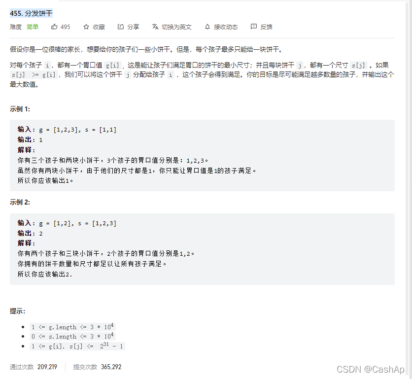
【ACM】455. Distribute Biscuits (1. Give priority to big biscuits to big appetite; 2. Traverse two arrays with only one for loop (use subscript index -- to traverse another array))

Deep learning classic network analysis and target detection (I): r-cnn
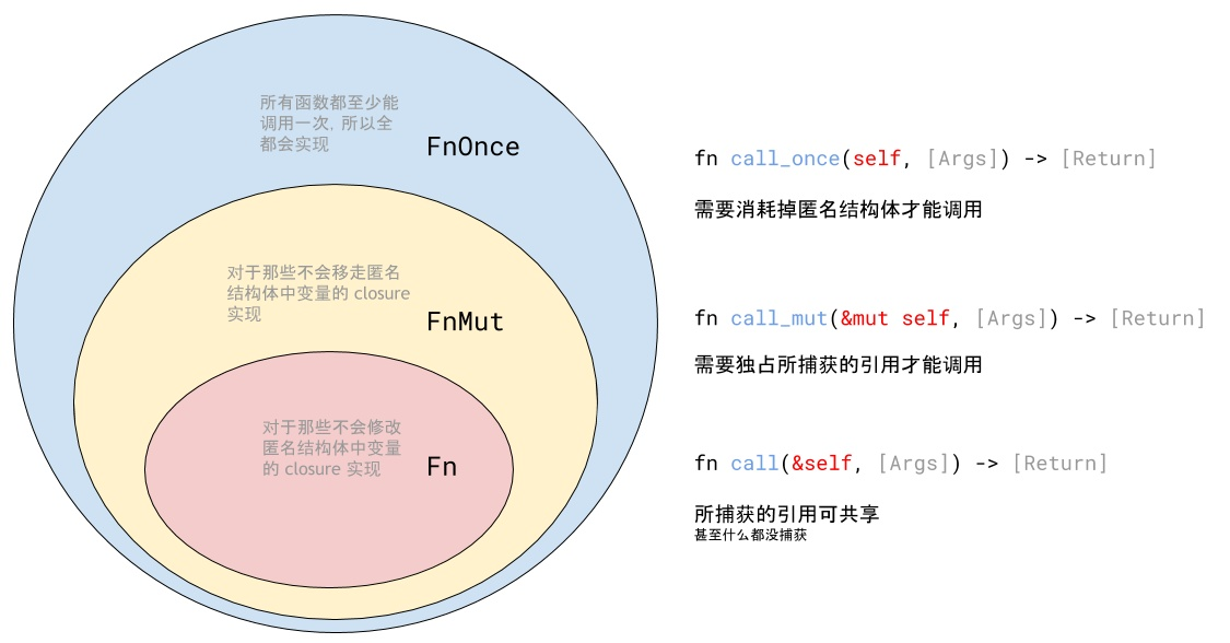
Closure type of rust (difference between FN, fnmut and fnone)

Robocode tutorial 3 - Robo machine analysis
Docker 安装 Redis
Matlab tips (6) comparison of seven filtering methods
STM32学习记录0008——GPIO那些事1
随机推荐
Daily network security certification test questions (April 13, 2022)
深度学习经典网络解析目标检测篇(一):R-CNN
Hard core parsing promise object (do you know these seven common APIs and seven key questions?)
Analysez l'objet promise avec le noyau dur (Connaissez - vous les sept API communes obligatoires et les sept questions clés?)
Climbing watermelon video URL
Daily network security certification test questions (April 18, 2022)
【ACM】70. 爬楼梯
Ionic 从创建到打包指令集顺序
Gson fastjason Jackson of object to JSON difference modifies the field name
In shell programming, the shell file with relative path is referenced
Crawling mobile game website game details and comments (MQ + multithreading)
Calculation of fishing net road density
QT reading and writing XML files (including source code + comments)
CISSP certified daily knowledge points (April 12, 2022)
According to the result set queried by SQL statement, it is encapsulated as JSON
Crawl the product data of Xiaomi Youpin app
ArcGIS license error -15 solution
Rust: how to implement a thread pool?
Rust: how to match a string?
logstash 7. There is a time problem in X. the difference between @ timestamp and local time is 8 hours