当前位置:网站首页>Arm architecture assembly instructions, registers and some problems
Arm architecture assembly instructions, registers and some problems
2022-04-23 20:59:00 【Descosmos】
List of articles
ARM
register
1. General registers
31 General registers (R0~R30), Each register can access one 64 Number of bit sizes , When using X0-X30 when , It's a 64 The number of bits , When using W0-W30 During the interview , It's a 32 The number of bits , Is the low of the register 32 position .
[ Failed to transfer the external chain picture , The origin station may have anti-theft chain mechanism , It is suggested to save the pictures and upload them directly (img-YKx2zhAq-1628126375081)(./ General registers 1.png)]
2. Vector register
( You could say Floating point register ) The size of each register is 128 Bit . Can be used separately Bn、Hn、Sn、Dn、Qn The way to access different bits .
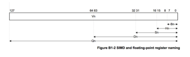
As can be seen from the figure :
- Bn: One Byte Size , namely 8 position ;
- Hn: half word, namely 16 position ;
- Sn: single word, namely 32 position ;
- Dn: double word, namely 64 position ;
- Qn: quad word, namely 128 position .
3. Special register
- sp: (Stack Pointer), Top register , Used to save the stack top address ;
- fp(x29): (Frame Pointer) Register... For the stack base address , Used to save the address at the bottom of the stack ;
- lr(x30): (Link Register) , Save call jump instruction bl The memory address of the next instruction of the instruction ;
- zr(x31): (Zero Register),xzr/wzr Represent the 64/32 position , Its function is 0, Write in represents the result of discarding , Read it out to be 0;
- pc: Save the address of the instruction to be executed ( There is an operating system that determines its value , Can't rewrite ).
4. Status register CPSR
CPSR (Current Program Status Register) Unlike other registers , Other registers are used to store data , The whole register has a meaning ; and CPSR Registers work bit by bit , namely , Every one has a special meaning , Record specific information ; Here's the picture
notes : CPSR The register is 32 Bit .

- CPSR Of low 8 position ( Include I、F、T and M[4:0]) be called Control bits , The program cannot be modified , Unless CPU To run on Privilege mode Next , The program can modify the control bit .
- N、Z、C、V All condition code flags ; Its content can be changed by the result of arithmetic or logical operation , And you can decide whether an instruction is executed :
- N(Negative) sign : CPSR Of the 31 Is it N, Symbol sign bit ; Record whether the result is negative after the relevant instruction is executed , If it's negative , be N = 1; If it's a non negative number , be N = 0.
- Z(Zero) sign : CPSR Of the 30 Is it Z,0 Sign a ; Record the execution of relevant instructions , Whether the result is 0, If the result is 0, be Z = 1; If it doesn't 0, be Z = 0.
- C(Carry) sign : CPSR Of the 29 Is it C, Carry flag bit :
- Addition operation : When the result of the operation produces carry when ( Unsigned number overflow ),C = 1, otherwise C = 0 ;
- Subtraction ( Include CMP): When you do an operation, you get Borrow position when ( Unsigned number overflow ),C = 0, otherwise C = 1 .
- V(Overflow) sign : CPSR Of the 28 Is it V, overflow flag ; In a signed number operation , If it is beyond the scope that the machine can identify , It's called overflow .
ARM64 Appointment
x0 ~ x7 The front of the method will be stored separately 8 Parameters ; If the number of parameters exceeds 8 individual , Redundant parameters will be stored on the stack , The new method will read through the stack ;
The return value of the method is generally in x0 On ; If the return value of the method is a large data structure , The result will be x8 On the address of the execution .
Common instructions
MOV
Copy the value of one register to another ( It can only be used to transfer values between registers or between registers and constants , Cannot be used for memory address )
mov x1, x0 ; Register x0 Copy the value of to the register x1 in
ADD
Compare the value of one register with the value of another register Add up And save the result in another register
add x0, x0, #1    ;  Register  x0  Values and constants  1  After adding, it is saved in the register  x0  in
add x0, x1, x2    ;  Register  x1  and  x2  The values of are added and saved in the register  x0  in
add x0, x1, [x2]  ;  Register  x1  Add the value of the register  x2  As the address , Then take the contents of the memory address and put it into the register  x0  in
SUB
Compare the value of one register with the value of another register Subtracting the And save the result in another register
sub x0, x1, x2 ; Register x1 and x2 The value of is subtracted and saved in the register x0 in
MUL
Compare the value of one register with the value of another register Multiply And save the result in another register
mul x0, x1, x2 ; Register x1 and x2 The result is saved in the register after multiplying the value of x0 in
SIDV, UDIV
( Signed number , Corresponding udiv: An unsigned number ) Compare the value of one register with the value of another register be divided by And save the result in another register
sdiv x0, x1, x2 ; Register x1 and x2 After dividing the value of, the result is saved in the register x0 in
AND
Compare the value of one register with the value of another register Bitwise AND And save the result to another register
and x0, x0, #0xf ; Register x0 Values and constants 0xf Save to register after bitwise AND x0 in
ORR
Compare the value of one register with the value of another register Press bit or And save the result to another register
orr x0, x0, #9 ; Register x0 Values and constants 9 Save to register after bitwise OR x0 in
EOR
Compare the value of one register with the value of another register Bitwise XOR And save the result to another register
eor x0, x0, #0xf ; Register x0 Values and constants 0xf Save to register after bitwise XOR x0 in
STR
Write the value in the register to memory
str w9, [sp, #0x8] ; Register w9 Save the value in the stack memory [sp + 0x8] It's about
LDR
Read the value in memory into the register
ldr x0, [x1]          ;  Register  x1  As the address , Take the value of the memory address and put it into the register  x0  in
ldr w8, [sp, #0x8]    ;  Stack memory  [sp + 0x8]  The value at read to  w8  In the register
ldr x0, [x1, #4]!     ;  Register  x1  The value plus  4  As memory address ,  Take the value of the memory address and put it into the register  x0  in ,  Then register  x1  The value plus  4  Put in register  x1  in
ldr x0, [x1], #4      ;  Register  x1  As the memory address , Take the value of the memory address and put it into the register  x0  in ,  Then put the register  x1  The value plus  4  Put in register  x1  in
ldr x0, [x1, x2]      ;  Register  x1  And registers  x2  Add the values of as the address , Take the value of the memory address and put it into the register  x0  in
STP
Push instruction (str Variant instructions , You can operate two registers at the same time )
stp x29, x30, [sp, #0x10] ; take x29, x30 The value of the sp The offset 16 Byte position
LDP
Stack out instruction (ldr Variant instructions , You can operate two registers at the same time )
ldp x29, x30, [sp, #0x10] ; take sp The offset 16 Take out the value of one byte , Storage register x29 And registers x30
SCVTF, FCVTZS
SCVTF Convert signed fixed-point numbers to floating-point numbers
FCVTZS Floating point numbers Turn into Fixed-point number
scvtf	d1, w0      ;  Register  w0  Value ( Number of vertices , Turn it into   Floating point numbers )  Save to   Vector register / Floating point register  d1  in

fcvtzs w0, s0	    ;  Set the vector register  s0  Value ( Floating point numbers , convert to   Fixed-point number ) Save to register  w0  in
Comparison instruction
- CBZ: and 0 Compare (Compare), If the result is zero (Zero) Just transfer ( Can only jump to the next instruction )
- CBNZ: He Fei 0 Compare (Compare), If the result is not zero (Non Zero) Just transfer ( Can only jump to the next instruction )
- CMP: Comparison instruction , amount to subs, Affect program status register CPSR
Displacement command
- LSL: Logic shift left
- LSR: Logical shift right
- ASR: Count right
- ROR: Cycle moves to the right
Jump instruction
B: Jump to an address ( No return ), Will not change lr (x30) Register value ; It is generally a jump in this method , Such as while loop ,if else etc.
b LBB0_1 ; Jump directly to the label ‘LLB0_1’ Start execution
BL: Jump to an address ( There is a return ), Put the next instruction address first ( That is, the return address of the function ) Save to register lr (x30) in , Then jump ; It is generally used for direct calls to different methods
bl 0x100cfa754 ; Put the next instruction address first (‘0x100cfa754’ Return address after function call ) Save to register ‘lr’ in , Then call ‘0x100cfa754’ function
BLR: Jump to A register ( Value ) Address to ( There is a return ), Put the next instruction address first ( That is, the return address of the function ) Save to register lr (x30) in , Then jump
blr x20 ; Put the next instruction address first (‘x20’ The return address after the function call to ) Save to register ‘lr’ in , Then call ‘x20’ Function pointed to
BR: Jump to a register ( Value ) Address to ( No return ), Will not change lr (x30) Register value
RET: Subroutines ( Function call ) Return instruction , The return address is saved in the register by default lr (x30) in
problem 1
There is a c Function as follows , The main body of the assembly code is as follows :
void TestPushAndPop(){

    printf("Push an Pop !");
}
sub	sp, sp, #32             ;  Update the value of the stack top register ,( It can be seen that : apply  32  Bytes take up space for new use )
stp	x29, x30, [sp, #16]     ;  Save the value of the stack top register before calling the function and the address value of the next instruction to be executed after the function returns
add	x29, sp, #16            ;  Update the value of the bottom register ,( It can be seen that : Remnant  16  Byte space is used for this function )
adrp     x0, [email protected]        ;  obtain  ‘l_.str’  The address of the page where the label is located
add x0, x0, [email protected]	;  obtain  ‘l_.str’  The offset of the label corresponding to the page address
bl	_printf	                ;  call  ‘printf’  Function to print
stur	w0, [x29, #-4]          ;  take  w0  Register value ('bl'  The return value of the function call ) Save to  [x29 - 4]  In the memory address of
ldp	x29, x30, [sp, #16]     ;  Restore the value of the stack bottom register before calling the function
add	sp, sp, #32             ;  Restore the value of the stack top register before calling the function
ret													;  return
Yes, with the assembly code above , Allocated 32 Own space , among 16 Bytes are used as Into the stack, , The rest 16 Bytes are used to store temporary variables .
doubt : The example function is named without temporary variables , Why do you still need to apply for space ?
explain : Although the function has no temporary variables , But the call printf After the function , The compiler automatically adds This function returns the value To deal with , because arm64 Specifies that the integer return value is placed in x0 In the register ,
So there will be a local variable hidden int return_value; The statement is in , The temporary variable occupies 4 Byte space ; Again because arm64 For using sp When addressing as a base address ,
It has to be 16byte-alignment( alignment ), So I applied for 16 Byte space is used as a temporary variable .
版权声明
本文为[Descosmos]所创,转载请带上原文链接,感谢
https://yzsam.com/2022/111/202204210545297977.html
边栏推荐
- Deep analysis of C language pointer (Part I)
- matplotlib. Pyplot partition drawing
- 启牛学堂有用吗,推荐的证券账户是否安全
- MySQL基础之写表(创建表)
- Tensorflow1. X and 2 How does x read those parameters saved in CKPT
- Unit function expansion
- MySQL进阶之常用函数
- go struct
- Crisis is opportunity. Why will the efficiency of telecommuting improve?
- Mysql database common sense storage engine
猜你喜欢
Google tries to use rust in Chrome
MySQL进阶之数据的增删改查(DML)
Sharpness difference (SD) calculation method of image reconstruction and generation domain index
1.整理华子面经--1
Common commands of MySQL in Linux
thinkphp5+数据大屏展示效果
Problem brushing plan -- dynamic programming (IV)
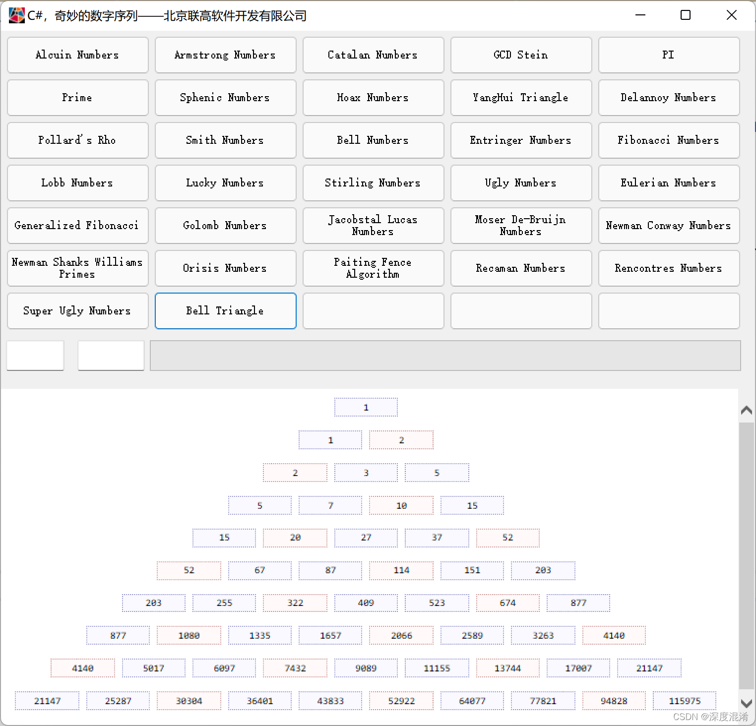
C#,打印漂亮的贝尔三角形(Bell Triangle)的源程序

亚马逊和Epic将入驻,微软应用商城向第三方开放

Is rust more suitable for less experienced programmers?
随机推荐
Problem brushing plan -- dynamic programming (IV)
Communication between RING3 and ring0
1.整理华子面经--1
Unity asset import settings
Thinkphp5 + data large screen display effect
GSI-ECM工程建设管理数字化平台
Addition, deletion, modification and query of MySQL advanced table
Rust更适合经验较少的程序员?
setInterval、setTimeout、requestAnimationFrame
C knowledge
Deno 1.13.2 发布
Fastdfs mind map
Presto on spark supports 3.1.3 records
Gsi-ecm digital platform for engineering construction management
setInterval、setTimeout、requestAnimationFrame
[matlab 2016 use mex command to find editor visual studio 2019]
PHP的Laravel与Composer部署项目时常见问题
matplotlib. Pyplot partition drawing
C#,打印漂亮的贝尔三角形(Bell Triangle)的源程序
Reentrant function