当前位置:网站首页>PWM speed regulation control system of DC motor based on 51 single chip microcomputer (with complete set of data such as Proteus simulation + C program)
PWM speed regulation control system of DC motor based on 51 single chip microcomputer (with complete set of data such as Proteus simulation + C program)
2022-04-23 14:24:00 【Jiang Yuzhi】
Design thinking
DC motor PWM The main functions of the control system include : It is easy to realize the acceleration of DC motor 、 Deceleration and forward rotation of motor 、 Reverse and emergency stop , And the speed of the motor can be adjusted , It can conveniently realize the intelligent control of motor .
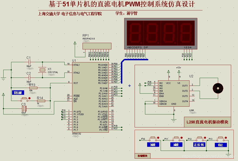
Main circuit : DC motor PWM Control module . This part of the circuit is mainly composed of AT89C52 Single chip microcomputer I/O port 、 Timing counter 、 External interrupt extension controls the acceleration of DC motor 、 Deceleration and forward and reverse rotation of motor , And the speed of the motor can be adjusted , It can easily realize the intelligent control of motor . In the meantime, through AT89C52 Single chip microcomputer generates pulse signal with adjustable pulse width and inputs it to L298 Driving chip to control the operation of DC motor .
The DC motor PWM The control system consists of the following circuit modules :
Design input part : The first mock exam is to use the independent keyboard with interrupt to accelerate the DC motor. 、 Deceleration and forward rotation of motor 、 Reverse and emergency stop control .
Design control part : Mainly by AT89C52 External interrupt expansion circuit of single chip microcomputer . DC motor PWM The control part is mainly realized by some diodes 、 Motors and L298 Composition of DC motor drive module .
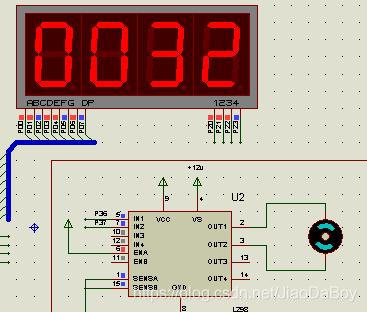
Design display part :LED Digital display part , Realize to PWM Real time display of PWM duty cycle .
System framework
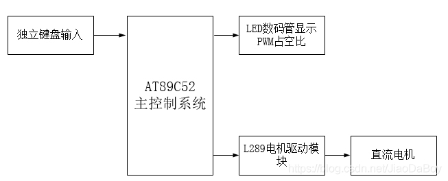
The principle is : DC motor PWM Speed regulation system AT89C52 Single chip microcomputer is the control core , By the command input module 、LED Display module and motor drive module . The independent keyboard with interrupt is used as the input of command , Single chip microcomputer under program control , Give regular and constant L298 DC motor drive chip sends PWM wave form ,H Type drive circuit completes the motor timing , Reverse and emergency stop control ; At the same time, the MCU keeps PWM PWM duty cycle LED Nixie tube completes real-time display .
Simulation circuit diagram
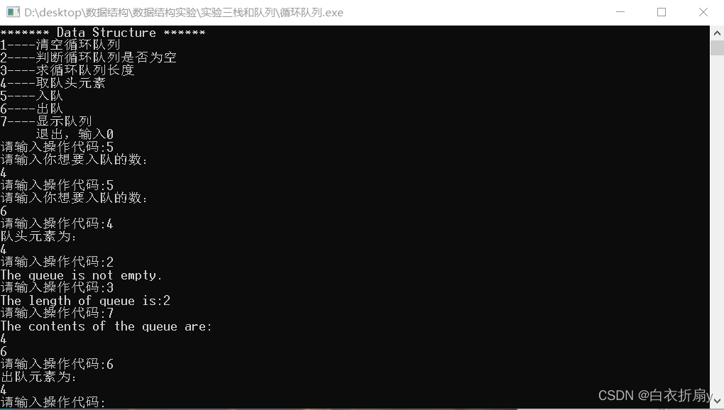
The simulation results are as follows
The design content is detailed , cover Single chip microcomputer minimum system design principle ; Key and nixie tube display design ;PWM Speed regulation principle 、 Method and implementation process ;L289 Design principle of motor drive chip ; complete Keil c Program The content such as . Let you know about DC motor PWM The design process of speed control system is clear at a glance .
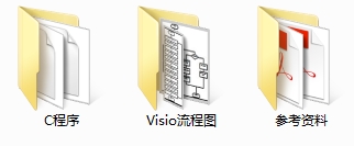
Resource sharing content
(1) be based on 51 Single chip microcomputer DC motor PWM Speed control system design paper ;
(2)Proteus Simulation file ;
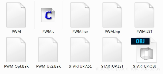
(3)Keil C Language program file ;
(4)L298 Driver chip technical manual and other reference materials ;
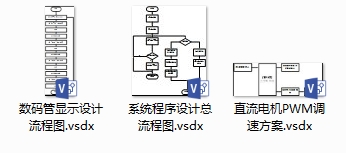
(5)Visio The flow chart drawn ;
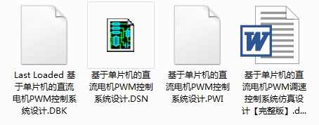
The screenshot of resources is as follows

Resource acquisition method
Resource acquisition method
Resource acquisition method !
Because this design is my original design , Get the complete Word Design report 、Proteus Simulation 、Keil C Program 、Visio Flow chart documents and references .
WeChat search for my official account : Jiaoyuan Xiaozhi
版权声明
本文为[Jiang Yuzhi]所创,转载请带上原文链接,感谢
https://yzsam.com/2022/04/202204231412472028.html
边栏推荐
- Introduction to the use of semaphore for inter thread control
- Logical volume creation and expansion
- 修改Firebase Emulators的默认侦听IP
- JS format time
- 常见存储类型和FTP主被动模式解析
- Upgrade of openssh and modification of version number
- 如何5分钟上手使用OCR
- Use of ansible and common modules
- How does void * exist?
- Golang 对分片 append 是否会共享数据
猜你喜欢

ArrayList集合基本使用
循环队列的基本操作(实验)
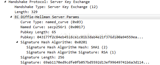
TLS/SSL 协议详解 (28) TLS 1.0、TLS 1.1、TLS 1.2之间的区别
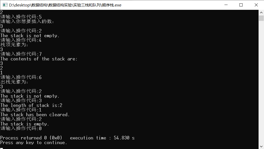
顺序栈的基本操作
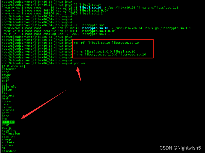
统信UOS卸载php7.2.24,安装php7.4.27 ;卸载再安装为PHP 7.2.34
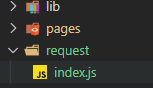
微信小程序将原生请求通过es6的promise来进行优化
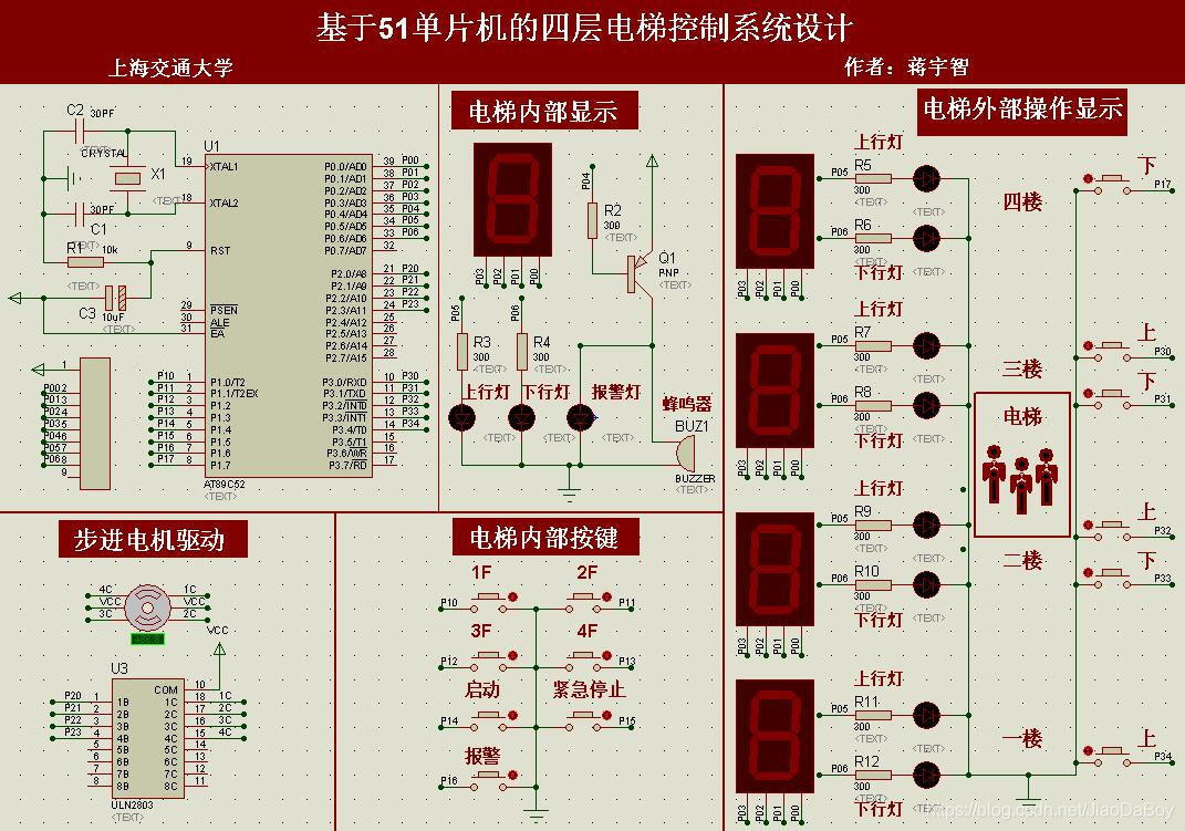
四层和八层电梯控制系统Proteus仿真设计,51单片机,附仿真和Keil C代码
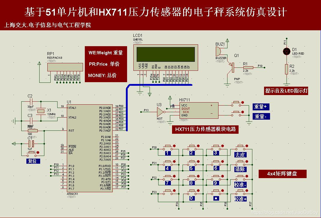
电子秤称重系统设计,HX711压力传感器,51单片机(Proteus仿真、C程序、原理图、论文等全套资料)
Tongxin UOS uninstall php7 2.24, install php7 4.27 ; Uninstall and then install PHP 7.2.34
Visio画拓扑图随记
随机推荐
flannel 原理 之 子网划分
矩阵交换行列
Redis cluster 原理
八路抢答器系统51单片机设计【附Proteus仿真、C程序、原理图及PCB文件、元器件清单和论文等】
source insight via samba
async void 导致程序崩溃
流程控制之分支语句
Introduction to loan market quotation interest rate (LPR) and loan benchmark interest rate
LLVM - 生成 if-else 以及 PH
API Gateway/API 网关(二) - Kong的使用 - 负载均衡Loadbalance
微信小程序轮播图swiper
asp.net使用MailMessage发送邮件的方法
Date的after时间判断
交通灯系统51单片机设计(附Proteus仿真、C程序、原理图及PCB、论文等全套资料)
关于在vs中使用scanf不安全的问题
A table splitting implementation scheme of MySQL and InnoDB, MyISAM and MRG_ Introduction to MyISAM and other engine application scenarios
js 递归(1)
剑指offer刷题(2)--面向华为
AT89C52单片机的频率计(1HZ~20MHZ)设计,LCD1602显示,含仿真、原理图、PCB与代码等
OpenSSH的升级、版本号的修改