当前位置:网站首页>STM32__ 03 - beginner timer
STM32__ 03 - beginner timer
2022-04-23 16:46:00 【The God of C language】
One ,TIM brief introduction
TIM The essence of is the counter , Count the input clock , The reference clock is the main frequency 72MHZ, Without frequency division, it can generate 72M Pulse .TIM Sub advanced , Universal , Basic timer , I'm using f102c8t6 Only TIM1~TIM4 Four timers , among TIM1 For advanced timer , Others are general timers , This time mainly focuses on the general timer .
1, General timer internal structure
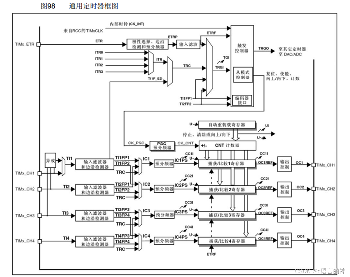
On the left is the clock input , This time we mainly understand TIMx_ETR External clock and internal clock TIMxCLK,TIMx_CH1, Capture... For input , This time does not involve .
The above structure is too complex. Here we refer to B A picture made by Jiangke University
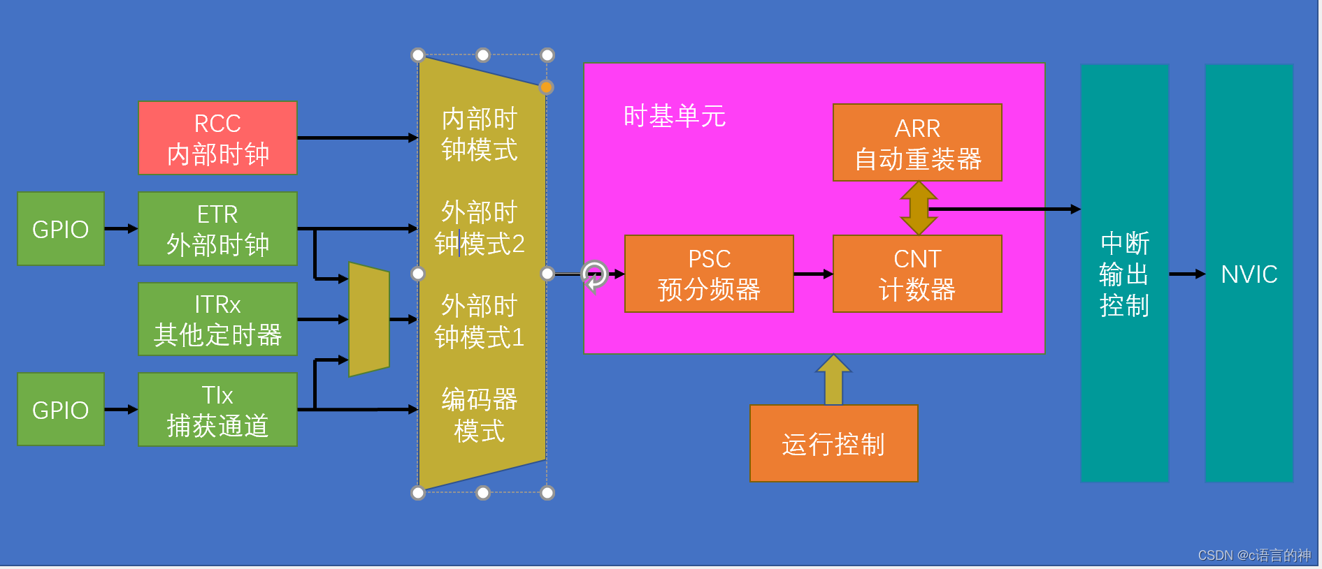
For this picture , We just need to initialize the timer from left to right
2, Initialize the timer
1) First, enable the internal clock . Turn on TIM2( Used this time is TIM) The clock , Use internal clock mode .
The functions used are :
RCC_APB1PeriphClockCmd(RCC_APB1Periph_TIM2,ENABLE);
Both basic and general timers are connected to APB1 Bus , The advanced timer is connected to APB2 Bus .
TIM_InternalClockConfig(TIM2);
Use the internal clock , Even if this function is not called, the system uses the internal clock by default .
2) Configuration of time base unit , And configuration GPIO be similar , It is to configure structural variables
TIM_TimeBaseInitTypeDef TIM_TimerBaseStructure;
Define the structure variable name
TIM_TimerBaseStructure.TIM_ClockDivision=TIM_CKD_DIV1;
The clock frequency division , Not used here .
TIM_TimerBaseStructure.TIM_CounterMode=TIM_CounterMode_Up ;
counter mode , Here, select the normal up count
TIM_TimerBaseStructure.TIM_Period=10000-1;
Yes ARR Automatic reloader for configuration
TIM_TimerBaseStructure.TIM_Prescaler=7200-1;
Yes PSC The prescaler is configured
Be careful : Here we use a timed one second operation , You can refer to the formula

-1 To eliminate errors , We can understand that , The frequency of the internal clock is 72MHZ, First use the prescaler to divide into 7200 Share , So each is 10000HZ, Then we use a capacity of 10000 To calculate the pulse ,10000HZ Generate... For one second 10000 Pulse , In this way, the counter is filled up in one second , Create spillover .
TIM_TimerBaseStructure.TIM_RepetitionCounter=0;
Repeat counter , Advanced timer , We have... Here 0.
TIM_TimeBaseInit(TIM2,&TIM_TimerBaseStructure);
Call initialization function , Complete the configuration of time base unit
3) Interrupt enable
TIM_ClearFlag(TIM2,TIM_FLAG_Update);
This function clears the interrupt flag bit , Why this extra step ? We can have a look TIM_TimeBaseInit() The definition of

Generate an update event immediately to reload the prescaler and repeat counter values , It can be understood as , An update event will be generated immediately after initializing the time base unit , Cause interrupt flag position 1, Enter the interrupt function immediately after reset , Will cause the program to run one step ahead , So don't forget this step after initializing the time base unit .
TIM_ITConfig(TIM2,TIM_IT_Update,ENABLE);
Update interrupted to NVIC
4)NVIC Configuration of
NVIC_PriorityGroupConfig(NVIC_PriorityGroup_2);
NVIC Priority groups
NVIC_InitTypeDef NVIC_InitStructure;
Structure variable naming
NVIC_InitStructure.NVIC_IRQChannel=TIM2_IRQn ;
Timer TIM2 stay NCIV Interrupt channel
NVIC_InitStructure.NVIC_IRQChannelCmd=ENABLE;
Channel enable
NVIC_InitStructure.NVIC_IRQChannelPreemptionPriority=2;
priority
NVIC_InitStructure.NVIC_IRQChannelSubPriority=1;
priority
NVIC_Init(&NVIC_InitStructure);
NVIC Initialization function
TIM_Cmd(TIM2,ENABLE);
Enable or disable the specified TIM peripherals
5) Interrupt the call of the service function
void TIM2_IRQHandler();
A complete timer initialization is complete .
Two , Code section
1,Timer.c
#include "stm32f10x.h"                  // Device header


void Timer_Init()
{
	RCC_APB1PeriphClockCmd(RCC_APB1Periph_TIM2,ENABLE);// Turn on TIM2 The clock , Note that APB1Z Bus

	TIM_InternalClockConfig(TIM2);// After power on, the internal clock is used by default , But for the integrity of the program , Still called this function

	// Initialization of time base unit
	TIM_TimeBaseInitTypeDef TIM_TimerBaseStructure;
	TIM_TimerBaseStructure.TIM_ClockDivision=TIM_CKD_DIV1;// The clock frequency division , Filtering uses
	TIM_TimerBaseStructure.TIM_CounterMode=TIM_CounterMode_Up ;// Count up
	TIM_TimerBaseStructure.TIM_Period=10000-1;//ARR The value of the automatic reloader
	TIM_TimerBaseStructure.TIM_Prescaler=7200-1;//PSC Value of prescaled frequency
	// Here can be understood as giving 72MHZ Signal division 7200 Share , Each one is 10000hz, Then use a capacity of 10000 The container of
	// Go and pack , Each fill is 1S
	TIM_TimerBaseStructure.TIM_RepetitionCounter=0;// Repeat counter , Advanced timer
	TIM_TimeBaseInit(TIM2,&TIM_TimerBaseStructure);
	// To interrupt
	TIM_ClearFlag(TIM2,TIM_FLAG_Update);
	TIM_ITConfig(TIM2,TIM_IT_Update,ENABLE);// Update interrupted to NVIC
	//NVIC To configure
	NVIC_PriorityGroupConfig(NVIC_PriorityGroup_2);//NVIC Priority groups
	NVIC_InitTypeDef NVIC_InitStructure;
	NVIC_InitStructure.NVIC_IRQChannel=TIM2_IRQn ;// Timer TIM2 stay NCIV Interrupt channel
	NVIC_InitStructure.NVIC_IRQChannelCmd=ENABLE;
	NVIC_InitStructure.NVIC_IRQChannelPreemptionPriority=2;// priority
	NVIC_InitStructure.NVIC_IRQChannelSubPriority=1;// priority
	NVIC_Init(&NVIC_InitStructure);
	// Start timer
	TIM_Cmd(TIM2,ENABLE);
}
// Interrupt service function
//void TIM2_IRQHandler()
//{
//	if(TIM_GetITStatus(TIM2,TIM_IT_Update)==SET)
//	{
//		TIM_ClearITPendingBit(TIM2,TIM_IT_Update);
//	}
//}
2,oled.c
#include "stm32f10x.h"                  // Device header
void LED_Init()
{
	RCC_APB2PeriphClockCmd(RCC_APB2Periph_GPIOA,ENABLE);
	GPIO_InitTypeDef GPIO_InitStructure;
	GPIO_InitStructure.GPIO_Mode=GPIO_Mode_Out_PP;
	GPIO_InitStructure.GPIO_Pin=GPIO_Pin_1 | GPIO_Pin_2;
	GPIO_InitStructure.GPIO_Speed=GPIO_Speed_50MHz;
	GPIO_Init(GPIOA,&GPIO_InitStructure);
	GPIO_SetBits(GPIOA,GPIO_Pin_1 | GPIO_Pin_2);
}
void LED1_ON()
{
	GPIO_ResetBits(GPIOA,GPIO_Pin_1);
}
void LED1_OFF()
{
	GPIO_SetBits(GPIOA,GPIO_Pin_1);
}
void LED1_Turn()
{
	if(GPIO_ReadOutputDataBit(GPIOA,GPIO_Pin_1)==0)
	{
		GPIO_SetBits(GPIOA,GPIO_Pin_1);
	}
	else
	{
		GPIO_ResetBits(GPIOA,GPIO_Pin_1);
	}
}
void LED2_Turn()
{
	if(GPIO_ReadOutputDataBit(GPIOA,GPIO_Pin_2)==0)
	{
		GPIO_SetBits(GPIOA,GPIO_Pin_2);
	}
	else
	{
		GPIO_ResetBits(GPIOA,GPIO_Pin_2);
	}
}
void LED2_ON()
{
	GPIO_ResetBits(GPIOA,GPIO_Pin_2);
}
void LED2_OFF()
{
	GPIO_SetBits(GPIOA,GPIO_Pin_2);
}
3,main.c
#include "stm32f10x.h"                  // Device header
#include "Delay.h"
#include "LED.h"
#include "Key.h"
#include "Buzzer.h"
#include "OLED.h "
#include "Timer.h"

uint16_t Num;

int main()
{
	OLED_Init();

   Timer_Init();
	OLED_ShowString(1,1,"Num:");


	while(1)
	{

		OLED_ShowNum(1,5,Num,5);
		OLED_ShowNum(2,5,TIM_GetCounter(TIM2),5);
	}

}
void TIM2_IRQHandler()
{
	if(TIM_GetITStatus(TIM2,TIM_IT_Update)==SET)
	{
		Num++;
		TIM_ClearITPendingBit(TIM2,TIM_IT_Update);
	}
}
Realization Num Add per second 1, And display on the screen .
3、 ... and , summary
stm32 It took a long time to figure out . Everything is difficult at the beginning , But I didn't know it would be so difficult .
版权声明
本文为[The God of C language]所创,转载请带上原文链接,感谢
https://yzsam.com/2022/04/202204231640379753.html
边栏推荐
猜你喜欢
Ali developed three sides, and the interviewer's set of combined punches made me confused on the spot
详解牛客----手套
Summary according to classification in sail software
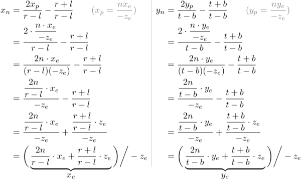
∑GL-透视投影矩阵的推导
LVM与磁盘配额

如何建立 TikTok用户信任并拉动粉丝增长
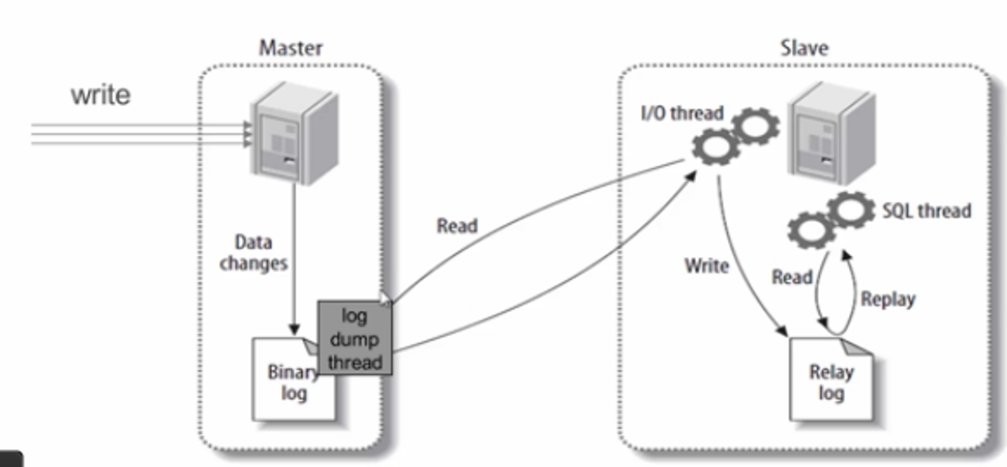
MySQL master-slave replication
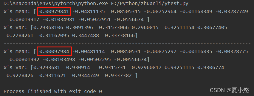
Pytorch: the pit between train mode and eval mode
MySql主从复制
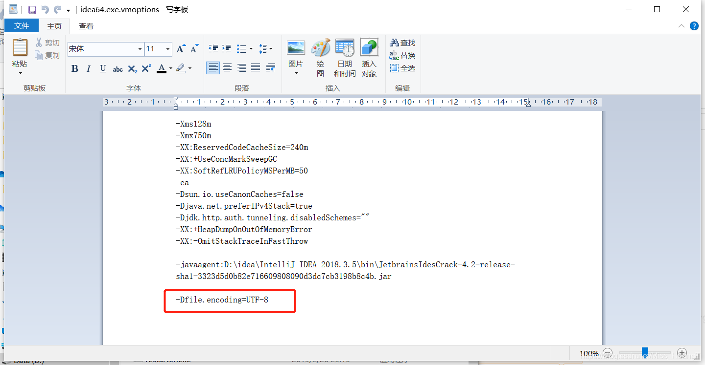
Solution of garbled code on idea console
随机推荐
STM32__03—初识定时器
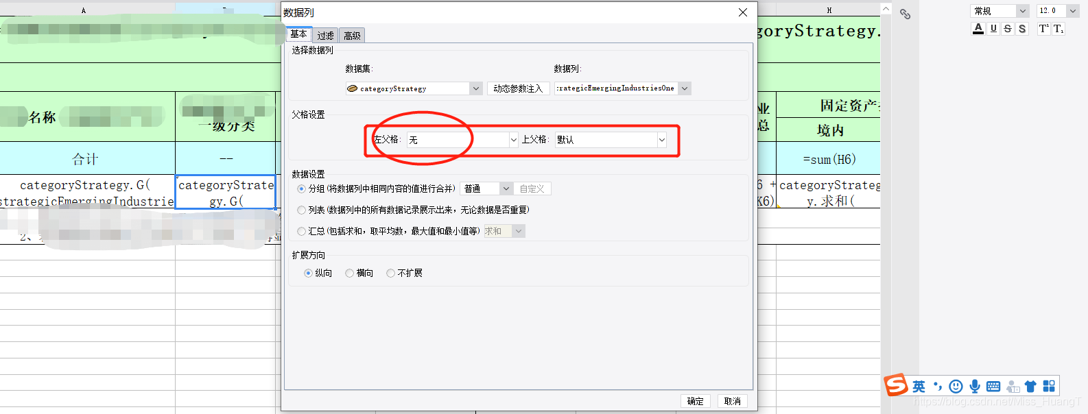
Set cell filling and ranking method according to the size of the value in the soft report
Xinwangda: HEV and Bev super fast charging fist products are shipped on a large scale
How magical is the unsafe class used by all major frameworks?
Use case labeling mechanism of robot framework
Use case execution of robot framework
伪分布安装spark
NVIDIA显卡驱动报错
Encapsulating the logging module
Project framework of robot framework
织梦DEDECMS安全设置指南
Deepinv20 installation MariaDB
Selenium IDE and XPath installation of chrome plug-in
Real time operation of vim editor
The font of the soft cell changes color
04 Lua operator
05 Lua control structure
05 Lua 控制结构
Detailed explanation of Niuke - Gloves
Take according to the actual situation, classify and summarize once every three levels, and see the figure to know the demand