当前位置:网站首页>MCU function signal generator, output four kinds of waveforms, adjustable frequency, schematic diagram, simulation and C program
MCU function signal generator, output four kinds of waveforms, adjustable frequency, schematic diagram, simulation and C program
2022-04-23 14:25:00 【Jiang Yuzhi】
The design requirements
-
With MCS-51 Series single chip microcomputer is the control device , use C Language for program development , Combined with peripheral electronic circuits , Design a function signal generator system ;
-
Can produce a sine wave 、 square wave 、 Triangular wave and sawtooth wave 4 Kinds of waveform ;
-
Extended keyboard input circuit , Used to switch the waveform type 、 Set the frequency size and step value ;
-
LCD1602 The display circuit displays the current waveform type in real time 、 Frequency value and other information ;
-
Adjustment range of waveform frequency value :10~100Hz;
-
Frequency step value adjustment range :0.1~10Hz;
System Overview
This article is based on 51 Function signal generator system designed by single chip microcomputer , Can produce a sine wave 、 square wave 、 Triangular wave and sawtooth wave 4 Kinds of waveform , And the waveform frequency is adjustable , The adjustment range is 10~100Hz.
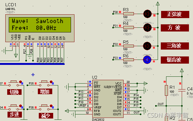
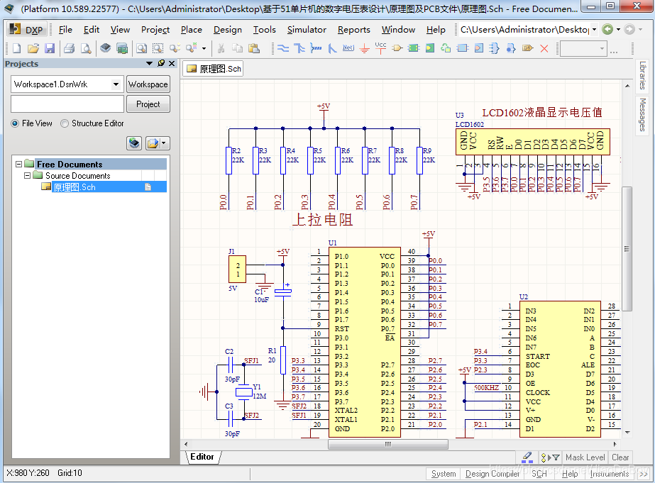
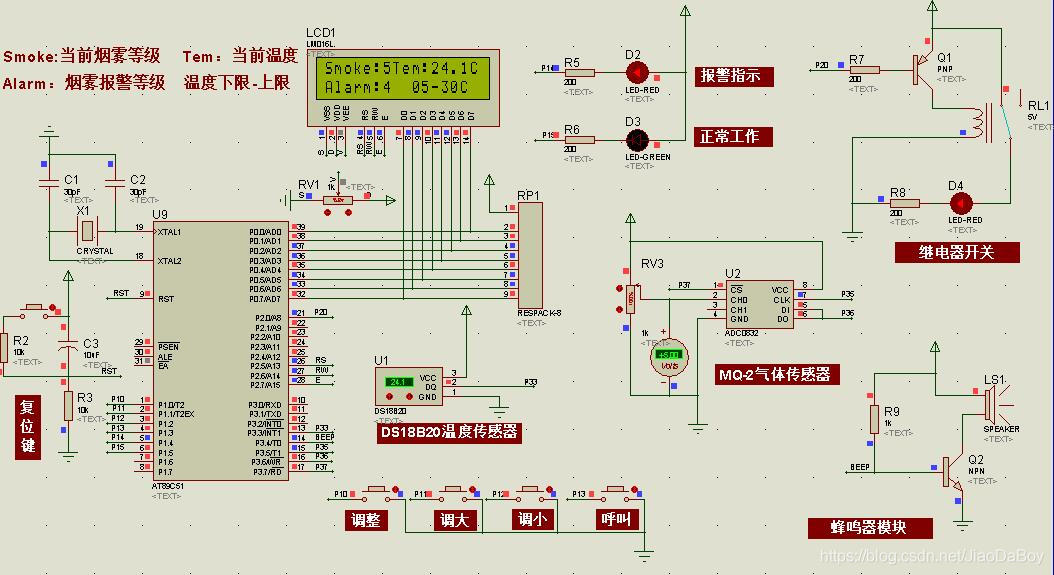
System consists of 5V Power supply module 、AT89C51 Minimum system of single chip microcomputer 、DAC0832 A / D conversion circuit 、LM358 Amplification circuit 、LCD1602 LCD circuit 、 Key circuit and LED The indicator circuit consists of .
The system framework is as follows :
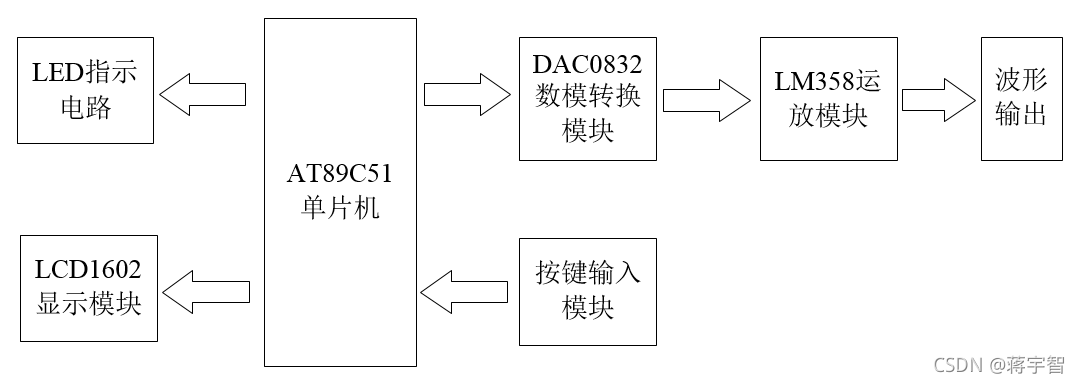
Working principle is : Digital signal generated by single chip microcomputer , the DAC0832 Convert to analog signal , Re pass LM358 After the operation circuit is amplified , Output 4 A waveform with adjustable frequency .
The type and frequency value of the waveform are determined by LCD Liquid crystal display (LCD) , The switching of waveform and the adjustment of frequency are controlled by keys . meanwhile ,4 A different color LED As indicator lights of different waveforms .
Simulation circuit diagram
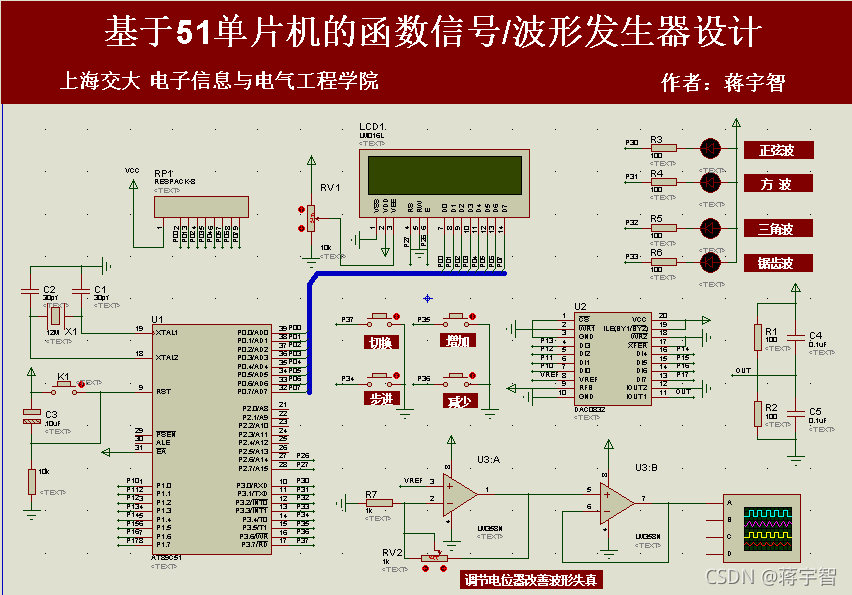
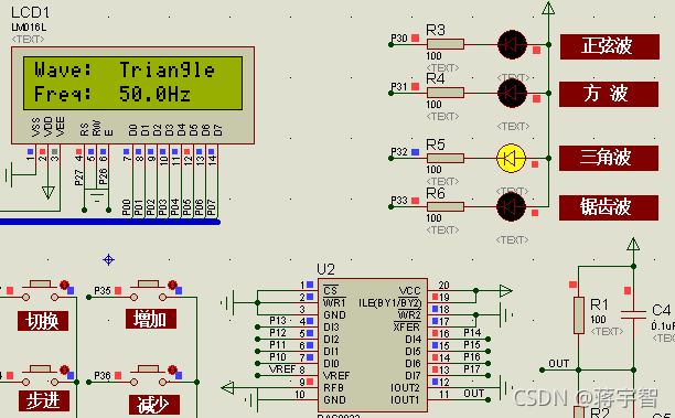
Schematic diagram
Analysis of simulation results
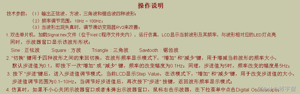
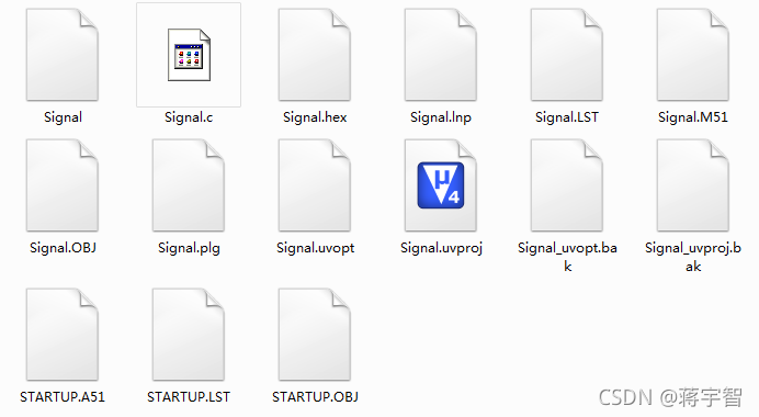
Open the function signal generator simulation file , Double click the MCU to load Signal.hex file ( be located C In the program folder ), Run the simulation , give the result as follows .
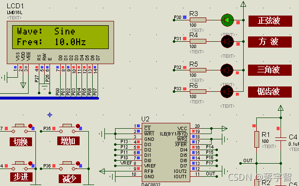
LCD1602 The first line of LCD shows Wave:Sine, The second line shows Freq:10.0Hz. Indicates that the current initialization waveform is 10Hz The sine wave of , At the same time, the green corresponding to the sine wave LED The light is on .
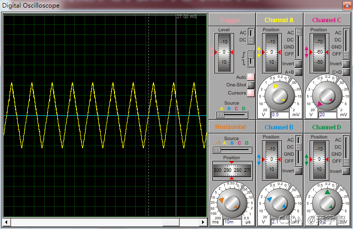
Besides , The system will pop up the oscilloscope window automatically , Display the waveform . In this system , The signal output terminal is connected to the... Of the oscilloscope A passageway .
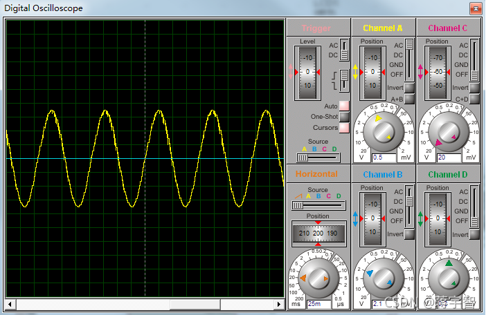
Simulation runtime , If the oscilloscope window is accidentally closed or does not pop up , Right click the oscilloscope , Click... In the drop-down menu Digtal Oscilloscope Can be restored .
In the system , Four keys are used to control the switching of waveform types 、 Increase or decrease of frequency value and increase or decrease of frequency step value .
Click on “ Switch ” key , Sine wave can be realized 、 square wave 、 Triangular wave and sawtooth wave 4 Switching back and forth between waveforms ;
In waveform frequency display mode ,“ increase ” and “ Reduce ” Key is used to increase or decrease the frequency of the current waveform , The default frequency step value of the system is 0.1, Press once “ increase ” or “ Reduce ” key , The change of frequency is 0.1Hz.
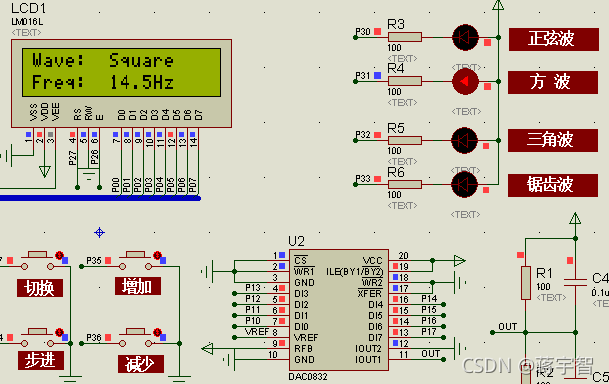
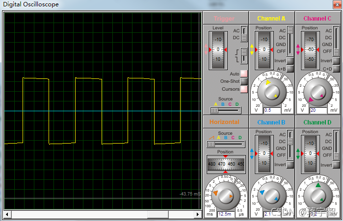
for example , We switch the waveform to square wave , Set its frequency to 14.5Hz, give the result as follows . here , Red corresponding to square wave LED The light is on .
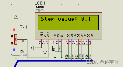
When pressed “ Stepping ” Post key , The system enters the step adjustment mode , As shown in the figure below .LCD Show Step value:0.1, Indicates that the current step value is 0.1Hz. here ,“ increase ” and “ Reduce ” key , Used to change the size of the step value .
for example , We set the frequency step value to 3Hz, The results are shown below . After setting , Press again “ Stepping ” key , The system exits the step adjustment mode , Return to frequency display mode . At this time , Press down “ increase ” or “ Reduce ” key , The change amplitude of the frequency value is 3Hz.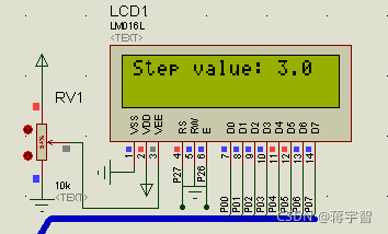
below , We set the system output frequency to 50Hz Triangular wave sum 80Hz The square wave , give the result as follows .
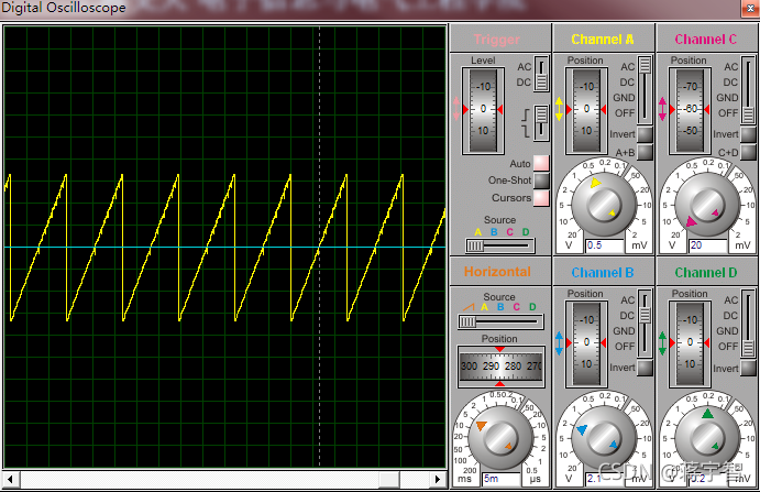
in summary , The operation effect of the function signal generator simulation circuit meets the design requirements , Verify success .
part C Code
void keyscan()					// Key scan function
{

	if(s1==0)					// Whether the frequency plus key is pressed
	{

		EA=0;					// Turn off interrupt
		delay(2);				// Delay chattering
		if(s1==0)				// Judge again
		{

			while(!s1);			// Release the button
			pinlv+=bujin;		// The frequency increases in steps
			if(pinlv>1000)		// The frequency value is maximum 100Hz
			{

				pinlv=100;
			}
			display();
/* The minimum frequency value is 10Hz,pinlv The value of is 100( Because you want to display one decimal place ),150000/100=1500, This 1500 That's what the timer needs to count , The unit is us,65536-1500 What you get is the initial value of the timer ,  Regardless of the initial value , Look at the timing first ,1500us, The period of a waveform is determined by 64 Composed of two timing , therefore , A waveform period is 64*1500us=96000, That is to say 96ms, Appointment etc   On 100ms, That is to say 10Hz The frequency of */
			m=65536-(150000/pinlv);	  // Calculate the frequency
			a=m/256;				  // Assign the initial value of the timer to the variable
			b=m%256;
			EA=1;					  // Turn on the interrupt master switch
		}
	}
	if(s2==0)					  // Whether the frequency reduction key is pressed
	{


		delay(5);
		if(s2==0)
		{

			EA=0;
			while(!s2);
			pinlv-=bujin;
			if(pinlv<100)
			{

				pinlv=1000;
			}
			display();
			m=65536-(150000/pinlv);
			a=m/256;
			b=m%256;
			EA=1;
		}
	}
	if(s3==0)					   // Whether the waveform switching key is pressed
	{

		delay(5);
		if(s3==0)
		{

			EA=0;
			while(!s3);
			boxing++;
			if(boxing>=4)
			{

				boxing=0;
			}
			display();
			EA=1;
		}
	}
}
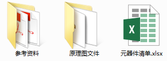
Resource content
(1) be based on 51 MCU function signal generator design paper complete version ;
(2)Keil C Program ;
(3)Proteus Simulation ;
(4) Schematic file ;
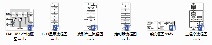
(5)Visio Flow chart file ;
(6) List of components ;
(7) Reference material ;
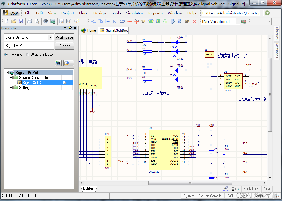
Resource screenshot

Say the important thing again !!!
Because the design of function signal generator is my original design , Get a full set of information ,
WeChat search for my official account : Jiaoyuan Xiaozhi
版权声明
本文为[Jiang Yuzhi]所创,转载请带上原文链接,感谢
https://yzsam.com/2022/04/202204231412471782.html
边栏推荐
猜你喜欢
AT89C51单片机的数字电压表开发,量程0~5V,proteus仿真,原理图PCB和C程序等
MQ-2和DS18B20的火灾温度-烟雾报警系统设计,51单片机,附仿真、C代码、原理图和PCB等
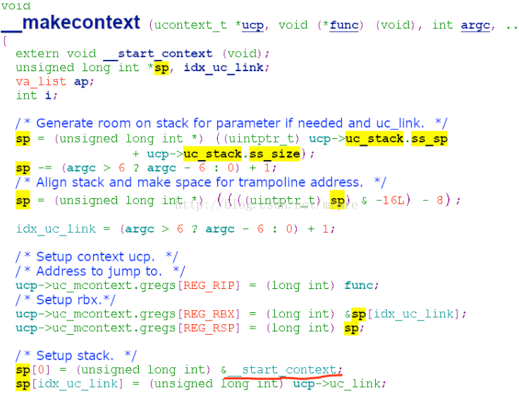
setcontext getcontext makecontext swapcontext
剑指offer刷题(1)--面向华为
进入新公司,运维工程师从下面这几项了解系统的部署
单片机的函数信号发生器,输出4种波形,频率可调,原理图,仿真和C程序
flannel 原理 之 TUN模式
LM317的直流可调稳压电源Multisim仿真设计(附仿真+论文+参考资料)
After entering the new company, the operation and maintenance engineer can understand the deployment of the system from the following items
剑指offer刷题(2)--面向华为
随机推荐
TLC5615 based multi-channel adjustable CNC DC regulated power supply, 51 single chip microcomputer, including proteus simulation and C code
Gif to still image processing
C语言知识点精细详解——数据类型和变量【1】——进位计数制
Redis cluster 原理
Introduction to the use of semaphore for inter thread control
KVM学习资源
进入新公司,运维工程师从下面这几项了解系统的部署
Quickly understand the three ways of thread implementation
分分钟掌握---三目运算符(三元运算符)
微信小程序轮播图swiper
Logical volume creation and expansion
Qt实战:云曦聊天室篇
Five ways of using synchronized to remove clouds and fog are introduced
Solve the problem of SSH configuration file optimization and slow connection
C语言知识点精细详解——初识C语言【1】——你不能不知的VS2022调试技巧及代码实操【1】
555定时器+74系列芯片搭建八路抢答器,30s倒计时,附Proteus仿真等
Web page, adaptive, proportional scaling
剑指offer刷题(1)--面向华为
TLS/SSL 协议详解 (28) TLS 1.0、TLS 1.1、TLS 1.2之间的区别
Electronic scale weighing system design, hx711 pressure sensor, 51 single chip microcomputer (proteus simulation, C program, schematic diagram, thesis and other complete data)