当前位置:网站首页>Application case of GPS Beidou high precision satellite time synchronization system
Application case of GPS Beidou high precision satellite time synchronization system
2022-04-23 15:45:00 【Anhui Jingzhun】
gps Application case of Beidou high precision satellite time synchronization system
gps Application case of Beidou high precision satellite time synchronization system
With the development of Beidou industry , The application scope of Beidou is gradually expanding , The number of application cases is also increasing . As a main application of Beidou system, high-precision timing synchronization is widely used in power system 、 signal communication 、 Radio and television 、 Defense and other fields .
One 、 Application case of satellite time synchronization system in Formosa Plastics thermal power plant system
The total investment of thermoelectric project of Formosa Plastics Group 31.6 Billion yuan , Among them, environmental protection investment accounts for a quarter of the total investment . Formosa Plastics thermal power plant was under construction , Desulfurization and dust removal equipment are installed synchronously ,2008 year 8 month , The first 3 This unit took the lead in putting denitration equipment into use in China .2015 - 2016 year , Formosa Plastics thermoelectric completed the transformation of ultra-low emission ahead of schedule , send 3 The coal-fired unit has reached the emission standard of natural gas unit .
The project is aimed at the transformation and upgrading of the satellite time synchronization device in phase I and phase II , The products of Anhui Jingzhun electric clock electronic technology Co., Ltd , Models for HR-901GB(2 Station master clock ,4 Expansion clock ). A screen is placed in the relay building of phase I and phase II ( contain 1 Master clock and 1 Expansion master clock )、#1 Put a screen in the electronic room of the machine ( contain 1 Expansion clock )、#2 Put a screen in the electronic room of the machine ( Contains an extended clock ),#3 Put a screen in the electronic room of the machine ( contain 1 Station master clock ) And #5 Put a screen in the electronic room of the machine ( contain 1 Expansion clock ).
The satellite time synchronization system consists of a master clock ( Standard synchronization clock body ) The device is composed of a clock signal expansion device and a time signal transmission channel . The antennas are respectively installed on the roof of phase I and phase II relay building and #3 Turbine roof . Optical fiber connection is adopted between the main clock device and the clock expansion device . Time synchronization system is mainly used in 500kV Control and protection equipment of booster station system ( It is mainly installed in the relay room of phase I and phase II relay building )、#1/#2 Unit control and protection equipment ( It is mainly installed in the centralized control building #1 Electronics room )、#3/#4 Unit control and protection equipment ( It is mainly installed in the centralized control building #4 Electronics room )、#5 Unit control and protection equipment ( It is mainly installed in the centralized control building #5 Electronics room ) Wait for the timing of secondary equipment .
The main clock and time synchronization signal expansion device equipment configured for the time synchronization system are used to realize the computer monitoring system in the power plant 、 Protector 、 Fault recorder 、DCS And time synchronization of desulfurization device and other equipment , Provide various time synchronization signals to meet the needs of these devices . The time synchronization system shall be able to receive Beidou satellite and data GPS Satellite signal as external time reference signal ( Beidou signal priority ), When the Beidou satellite is not received , Switch to GPS Satellite signal . Under normal circumstances , The time signal receiving units of the two master clocks independently receive Beidou satellite and satellite GPS The time reference signal sent by the satellite ; When the time signal receiving unit of a master clock fails , The master clock can automatically switch to the time reference signal received by the time signal receiving unit of another master clock , Realize that the time reference signals are standby for each other . The master clock shall have an internal guard clock , When the master clock receives the external time reference signal , Synchronized by an external time reference signal ; When the external time reference signal is not received , Keep a certain accuracy of travel time , So that the time synchronization signal output by the master clock can still maintain a certain accuracy . When the reception of the external time reference signal is restored , Automatically switch to normal operation , The switching time should be less than 0.5S, During switching, the time synchronization signal output by the master clock shall not be wrong . The time reference signal input of the time synchronization signal expansion screen shall receive two master clock signals at the same time , The two time reference signals are standby for each other . The main clock screen is configured to meet the interface required for the access of multi-channel time synchronization signal expansion screen . The output time signal meets the requirements of seconds (1PPS)、 branch (1PPM)、 when (1PPH)、IRIG-B(DC) time-frames 、IRIG-B(AC) Time code and serial port 、 Network interface, etc With time signal expansion function , In order to meet the different requirements of users, it is convenient to expand the output quantity of time synchronization signal . When the main clock equipment screen and clock signal expansion equipment screen have multiple time signal output , Regardless of the type of signal interface , All outputs are electrically isolated from each other . With working status indication 、 Alarm display and alarm signal output function .
The satellite time synchronization system is based on 《 Technical specification for unified clock system of East China power grid 》、《 Shanghai Power Grid GPS Technical principles and operation management regulations of time synchronization system 》 and 《 Technical specification for time synchronization of power system 》 Designed time synchronization system , It consists of master clock of time synchronization system and slave clock of time synchronization system , Can be centralized or separate group screen . The system uses GPS( Global positioning system )、 Beidou or IRIG-B(DC) Second synchronization signal and time information sent by code , Provide various systems and automation devices to the power system ( Such as dispatching automation system 、 Microcomputer relay protection device 、 Fault recorder 、 Sequence of events recording device 、 Telecontrol device 、 Computer data exchange network 、 Lightning location system, etc ) Provide accurate time information and time synchronization signal .
1.1 purpose
The main uses of satellite time synchronization system are as follows :
1、 The system is combined with the United States GPS、 Beidou, China 、 Russia's gronasi and other technical features, and considered various related factors related to national security , It realizes the input of multiple sources (GPS、 Beidou 、 Gloria 、 High precision punctuality 、IRIG-B Code reference, etc )、 Output multi standard (TTL、 Air contact 、IRIG-B、 Difference 、 A serial port 、 The Internet 、 Optical fiber, etc )、 Meet the requirements of multiple devices ( The system output can be expanded arbitrarily , It can meet any scale 、 Any kind of time signal demand ) The requirements of , Can be electricity 、 coal 、 Rail transit 、 Petroleum chemical industry 、 Waterway transportation 、 In the systems of posts, telecommunications and related fields, devices and systems that need to receive clock synchronization signals provide high precision 、 High stability 、 High security , Highly reliable time reference signal .
2、 Used by power companies at all levels ( Electric Power Bureau ) Authorities and subordinate dispatching offices 、 power plant 、 Wall clock of substation and other units .
1.2 characteristic
1、 High synchronization accuracy with external synchronization clock signal , The synchronization accuracy is better than ±0.2μs.
Multi synchronization source adaptive synchronization technology is adopted , The synchronization accuracy is better than ±0.2μs.
2、 Using redundant structure
Support double GPS Hot standby and dual IRIG-B Hot standby and equipped with high-precision punctual clock . The master clock of the time synchronization system can be accessed simultaneously GPS and 1 road IRIG-B Out of code synchronization signal , For each other . The time synchronization system can access from the clock at the same time 2 road IRIG-B Out of code synchronization signal , For each other . Redundancy devices can be used for both master clock and signal expansion device , To ensure the GPS Reliability and stability of time synchronization system .
3、 Modular design , Multiple output interfaces , It is flexible and convenient to use .
The output can meet IEEE STD 1344-1995 The standard IRIG-B(AC) code 、IRIG-B(DC) code 、 And definable time division second pulse null contact and time message information , Every time 12 The road is a group .2U The device can output up to 60 road ,4U The device can output up to 156 road .
use 2U or 4U 19” Standard case , The screen can be assembled separately , Support fiber or cable cascade input and output , It provides convenience for the expansion of satellite time synchronization signal in the future , Easy to maintain and manage .
4、 double CPU Parallel processing time message output technology
The output of time message adopts double CPU Parallel processing technology , The sending time of serial port message is seconds , The error is not greater than +0.2ms.
5、 High precision pulse output
Pulse output adopts pulse high current generation circuit , The photoelectric isolation empty contact can output high-precision pulse signal , The error is not greater than 3μs.
6、 High precision punctual clock
The closed-loop control punctuality technology is adopted to realize high-precision punctuality clock , use OCXO Punctuality accuracy can reach 0.6μs/min, use TCXO Punctuality accuracy can reach 15μs/min.
7、 Adopt no overshoot IRIG-B(AC) Code generation technology , Produce high-precision IRIG-B(AC) code , The accuracy can be as high as 5μs.
8、 Support NTP(Network Time Protocol, Network time protocol ) edition 4
9、LCD Display date and time and external synchronization information , With power grid frequency measurement function
10、 All signal output ports are photoelectric isolated , Electromagnetic anti-interference reaches III Class standards .
11、 There is an alarm contact output for monitoring the operation status of the device , Including power loss alarm 、 External synchronization signal disappearance alarm 、 And self inspection abnormal alarm of the device .
12、 Multi satellite system access and seamless handover between different systems , It ensures the safety and reliability of the time service system . At present, access is supported GPS、 Beidou 、 GLONASS and other satellite systems .
13、 Adapt to more networking modes , Mutual backup mode 、 Master-slave mode, etc . Flexible networking mode , It is suitable for dual clock or multi clock mutual standby 、 Clock, clock, etc .
14、 The equipment operation status can be through 104 Upload the protocol to the dispatching center
- Technical indicators
2.1 Physical parameters
2.1.1 The case
The master clock of time synchronization system and slave clock of time synchronization system adopt standard 19″ Rack cabinet , It can be firmly installed on the column in the distribution panel , The height is 2U or 4U. The chassis shell is provided with a reliable grounding point .
Dimensions :482.6mm(W)×260mm(L)×89mm(H)(2U)
482.6mm(W)×260mm(L)×178mm(H)(4U)
Yan color : Computer gray (RAL 7032) Or user specified .
heavy The amount :5kg
2U The case :
4U The case :
2.1.2 The antenna
The receiving antenna is matched with the mounting base .
Antenna size : The diameter of 95(mm)× Height 128(mm)
Base size : 90×30(mm)× Height 110(mm)
Base installation method : Male pipe thread , The inner diameter 24(mm)× Height 60(mm),
Installation position of base : roof , You can see most of the sky
weight ( Including mounting base ):3 kg
cable :RG-59 /RG-58 type , Standard length 30m, Or user specified .
2.2 Environmental conditions
2.2.1 Device working environment
working temperature :-25℃~ +55℃
Storage temperature :-40℃~ +85℃
Wet degree :5% ~ 95%, No condensation
2.2.2 Antenna working environment
working temperature :-40℃~ +80℃
Storage temperature :-45℃~ +90℃
Wet degree :100%, Condensation
2.3 Electromagnetic compatibility
The device can work normally under the electromagnetic field environment of substation protection room and control room , accord with “GB/T13926-1992 Electromagnetic compatibility of industrial process measurement and control devices ” Requirements of relevant provisions in , achieve Ⅳ Class standards .
Insulation performance : GB/T13926-2002 Ⅳ level
Anti high frequency interference : GB/T 15153.1-1998 Ⅳ level
Anti fast transient interference :GB/T 17626.4-1998 Ⅳ level
Antistatic discharge interference :GB/T 15153.1-1998 Ⅳ level
Anti power frequency magnetic field interference : GB/T 17626.8-1998 Ⅴ level
Anti pulse magnetic field interference : GB/T 17626.9-1998 Ⅴ level
Anti damping oscillation magnetic field interference : GB/T 17626.10-1998 Ⅴ level
Anti RF electromagnetic field radiation interference : GB/T 17626.3-1998 Ⅳ level
Anti surge interference : GB/T 15153.1-1998 Ⅳ level
2.4 Power supply
GPS The time synchronization system adopts AC and DC common power supply .
2.4.1 The ac power
Rated voltage : single-phase AC85-265V
frequency :50Hz, Permissible deviation ± 5Hz;
wave form : sine , The waveform distortion shall not be greater than 5%.
2.4.2 DC power supply
Rated voltage :DC100~280V;
Ripple coefficient :≤5%.
protective : Anti surge 、 Input filtering
2.4.3 Power consumption
No more than 50W.
2.5 Mean time between failures MTBF
Maintenance is not required under normal conditions of use .
MTBF: Not less than... Under normal conditions of use 50000h
2.6 Time signal input / output interface
2.6.1 Time signal reception ( Input )
1) Time synchronization system master clock
There is a way for the master clock of the time synchronization system GPS Interface and 1 road IRIG-B(DC RS-422) Time code interface . The first way IRIG-B The interface receives the signal sent by the master clock of another time synchronization system . It can also realize two wireless plus one wired input , Realize multi time source input .
When the master clock of the time synchronization system receives data normally at the same time GPS Satellite timing signals and signals IRIG-B(DC RS-422) Time code time ,GPS The second synchronization signal transmitted is used as the external time reference of the master clock ,IRIG-B(DC RS-422) Time code as backup . When GPS Out of step , The first way IRIG-B(DC) The time signal received by the interface is preferably used as the external time reference of the master clock .
GPS Satellite synchronization clock only supports one way GPS Interface or all the way IRIG-B Interface .
2) The time synchronization system starts from the clock
The slave clock of the time synchronization system is used when the time synchronization signal output by the master clock of the time synchronization system is insufficient , Provide required expansion units to meet the needs of different applications .
The time synchronization system has two channels from the time signal input of the clock IRIG-B(DC RS-422) Time code input . When the time synchronization system is connected only one way from the clock IRIG-B(DC RS-422) Time code input , This input can be IRIG-B(DC) Input 1, It can also be IRIG-B(DC) Input 2.
When the time synchronization system is connected to two channels from the clock IRIG-B(DC) Time code input , With IRIG-B(DC RS-422) Input 1 As the external time reference of the time scale extension device ,IRIG-B(DC RS-422) Input 2 As a backup .
2.6.2 Time signal output
Time synchronization system master clock 、 The time synchronization system can provide the following time synchronization signal outputs from the clock :
1)1PPS and 1PPM Pulse signal (TTL level ) Output , As a test port
2) Definable 1PPS、1PPM Pulse signal ( Air contact ) or 24V Active pulse output
2) Definable 1PPS、1PPM Pulse signal ( Differential signal , namely RS-422 level )
3) Time date message serial port (RS-232 or RS-422) Output
4)IRIG-B(DC RS-422) Time code output
5)IRIG-B(DC TTL) Time code output
6)IRIG-B(AC) Time code output
7)DCF77( Blank nodes ) Time code output
8) Frequency measurement data output
9)NTP Network output
The outputs are isolated from each other , The number of various synchronization signals can be combined according to actual needs , Each signal output interface can only be connected to one time service equipment . When there is no requirement for common land ,IRIG-B(DC RS-422) Each channel of time code output can be accessed 8 A time service device .
版权声明
本文为[Anhui Jingzhun]所创,转载请带上原文链接,感谢
https://yzsam.com/2022/04/202204231543449644.html
边栏推荐
猜你喜欢

建设星际计算网络的愿景
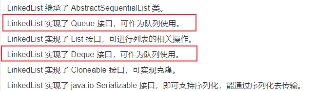
一刷314-剑指 Offer 09. 用两个栈实现队列(e)
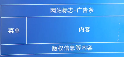
Basic concepts of website construction and management
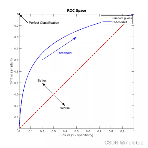
Recommended search common evaluation indicators
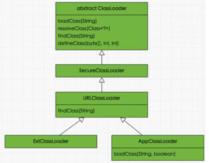
JVM-第2章-类加载子系统(Class Loader Subsystem)
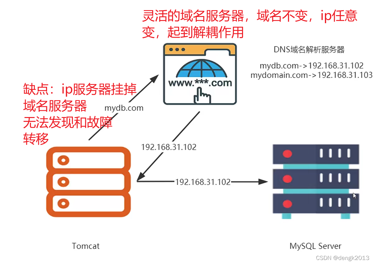
大型互联网为什么禁止ip直连
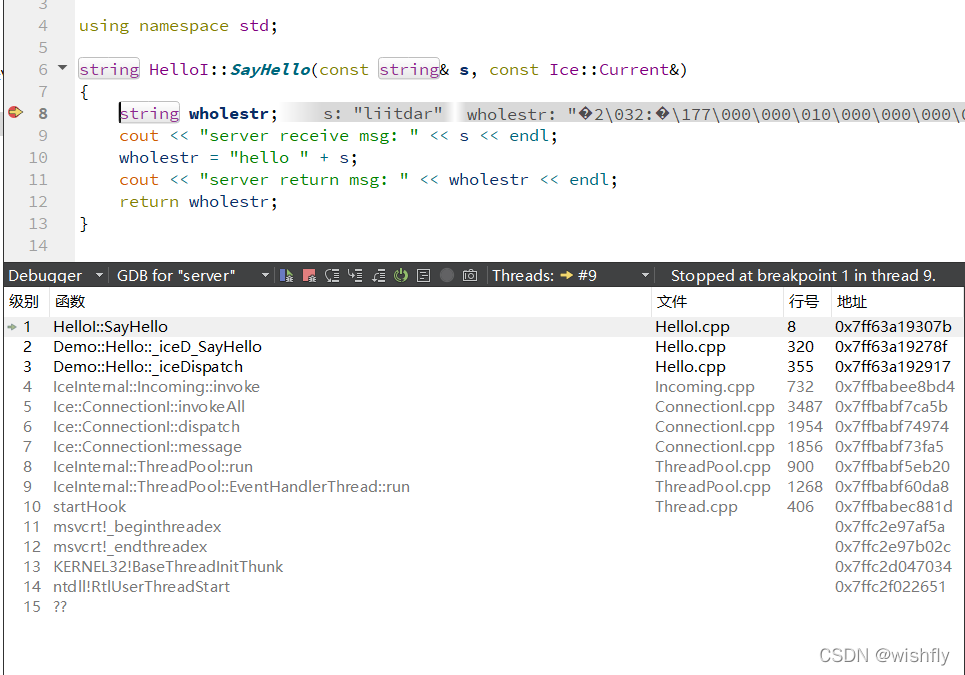
ICE -- 源码分析
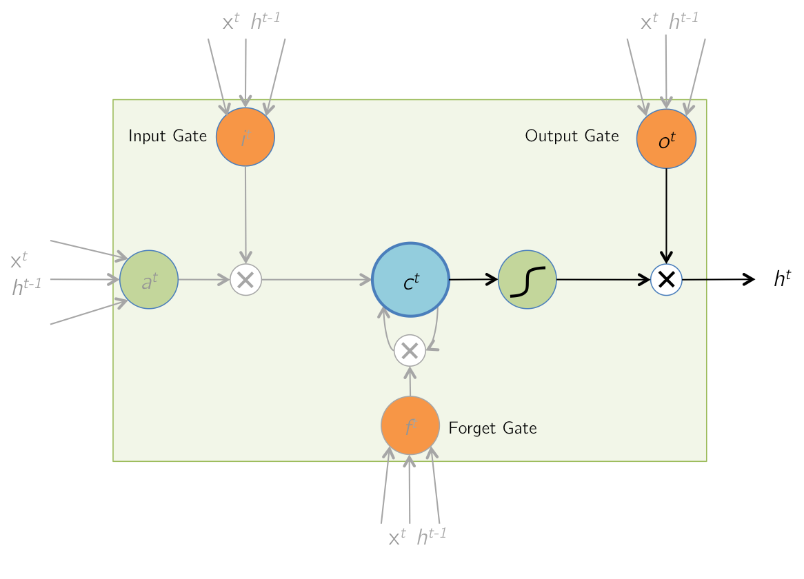
时序模型:长短期记忆网络(LSTM)
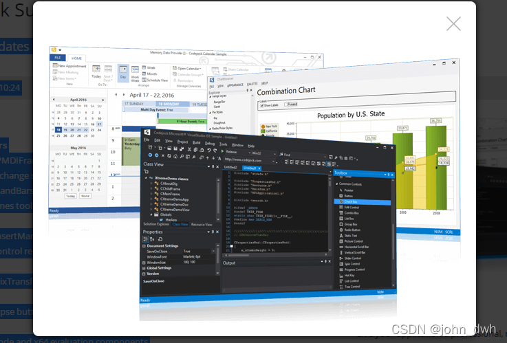
Codejock Suite Pro v20.3.0
Temporal model: long-term and short-term memory network (LSTM)
随机推荐
php函数
山寨版归并【上】
pgpool-II 4.3 中文手册 - 入门教程
【AI周报】英伟达用AI设计芯片;不完美的Transformer要克服自注意力的理论缺陷
Do we media make money now? After reading this article, you will understand
The El tree implementation only displays a certain level of check boxes and selects radio
怎么看基金是不是reits,通过银行购买基金安全吗
Recommended search common evaluation indicators
The principle and common methods of multithreading and the difference between thread and runnable
Go concurrency and channel
The length of the last word of the string
Fastjon2他来了,性能显著提升,还能再战十年
导入地址表分析(根据库文件名求出:导入函数数量、函数序号、函数名称)
Multi level cache usage
Open source project recommendation: 3D point cloud processing software paraview, based on QT and VTK
Treatment of idempotency
How did the computer reinstall the system? The display has no signal
一刷314-剑指 Offer 09. 用两个栈实现队列(e)
Neodynamic Barcode Professional for WPF V11.0
Fastjon2 here he is, the performance is significantly improved, and he can fight for another ten years