当前位置:网站首页>ESP32_ Arduino
ESP32_ Arduino
2022-04-23 15:55:00 【Sola_ Ex】
ESP32_Arduino
ESP32 GPIO Configuration of
From the official manual provided by Lexin ,ESP32 Of GPIO Basically universal GPIO, That is, except for a few special pins , Basically, each pin can be multiplexed into various functions , such as SPI/I2C wait .
-
Please note that ,GPIO6-11 Usually used for SPI Flash memory .
-
GPIO34-39 Can only be set to input mode , There is no software pull-up or pull-down function .
-
A separate “ RTC GPIO” Support , When GPIO Route to “ RTC” Low power consumption and analog subsystem , That support works . These pin functions can be used in the following cases :
- In deep sleep
- stay Ultra low power coprocessor function
- Analog functions such as ADC / DAC / Etc. in use .
The above paragraph is from the official of Lexin API course .
about ESP32 SDK Come on , contain GPIO Related are contained in gpio.c/gpio.h On , The use of correlation functions is similar to that of ordinary STM32 or NXP Our library is similar .
ESP32 GPIO_Arduino
Arduino It is a good set of hardware abstraction Library , be based on SDK On the basis of , Let all kinds of initialization functions do a unified encapsulation , Standardize interfaces . In fact, you just need to know what's relevant API Just call it .
frequently-used API Function has :
- pinMode(uint8_t pin, uint8_t mode)
- digitalWrite(uint8_t pin, uint8_t val)
- digitalRead(uint8_t pin)
- attachInterrupt(uint8_t pin, void ()(void), int mode);
- attachInterruptArg(uint8_t pin, void ()(void), void * arg, int mode);
- detachInterrupt(uint8_t pin);
pinMode It can make GPIO Initialize to the required mode , Such as input / Output, etc .
//GPIO FUNCTIONS
#define INPUT 0x01
#define OUTPUT 0x02
#define PULLUP 0x04
#define INPUT_PULLUP 0x05
#define PULLDOWN 0x08
#define INPUT_PULLDOWN 0x09
#define OPEN_DRAIN 0x10
#define OUTPUT_OPEN_DRAIN 0x12
#define SPECIAL 0xF0
#define FUNCTION_1 0x00
#define FUNCTION_2 0x20
#define FUNCTION_3 0x40
#define FUNCTION_4 0x60
#define FUNCTION_5 0x80
#define FUNCTION_6 0xA0
#define ANALOG 0xC0
about GPIO Come on , Simple input and output is not enough , It also needs to be used with interrupts , therefore Arduino The following interrupt mode options are provided .
//Interrupt Modes
#define DISABLED 0x00
#define RISING 0x01
#define FALLING 0x02
#define CHANGE 0x03
#define ONLOW 0x04
#define ONHIGH 0x05
#define ONLOW_WE 0x0C
#define ONHIGH_WE 0x0D
For additional reuse , Additional functions are also provided :
#define digitalPinIsValid(pin) ((pin) < 40 && esp32_gpioMux[(pin)].reg)
#define digitalPinCanOutput(pin) ((pin) < 34 && esp32_gpioMux[(pin)].reg)
#define digitalPinToRtcPin(pin) (((pin) < 40)?esp32_gpioMux[(pin)].rtc:-1)
#define digitalPinToAnalogChannel(pin) (((pin) < 40)?esp32_gpioMux[(pin)].adc:-1)
#define digitalPinToTouchChannel(pin) (((pin) < 40)?esp32_gpioMux[(pin)].touch:-1)
#define digitalPinToDacChannel(pin) (((pin) == 25)?0:((pin) == 26)?1:-1)
版权声明
本文为[Sola_ Ex]所创,转载请带上原文链接,感谢
https://yzsam.com/2022/04/202204231554163710.html
边栏推荐
- APISIX jwt-auth 插件存在错误响应中泄露信息的风险公告(CVE-2022-29266)
- dlopen/dlsym/dlclose的简单用法
- Application case of GPS Beidou high precision satellite time synchronization system
- Partitionby of spark operator
- 单体架构系统重新架构
- matplotlib教程05---操作图像
- The principle and common methods of multithreading and the difference between thread and runnable
- 一刷313-剑指 Offer 06. 从尾到头打印链表(e)
- Unity shader learning
- Large factory technology implementation | industry solution series tutorials
猜你喜欢
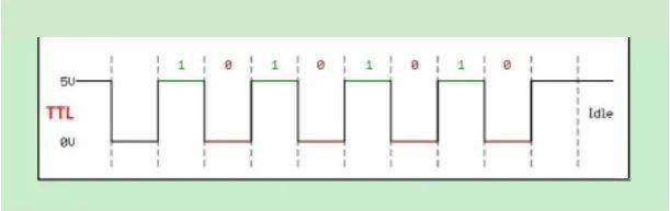
一文读懂串口及各种电平信号含义
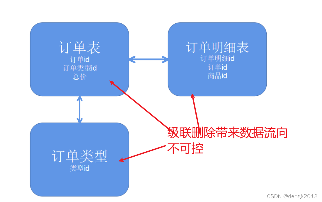
为啥禁用外键约束
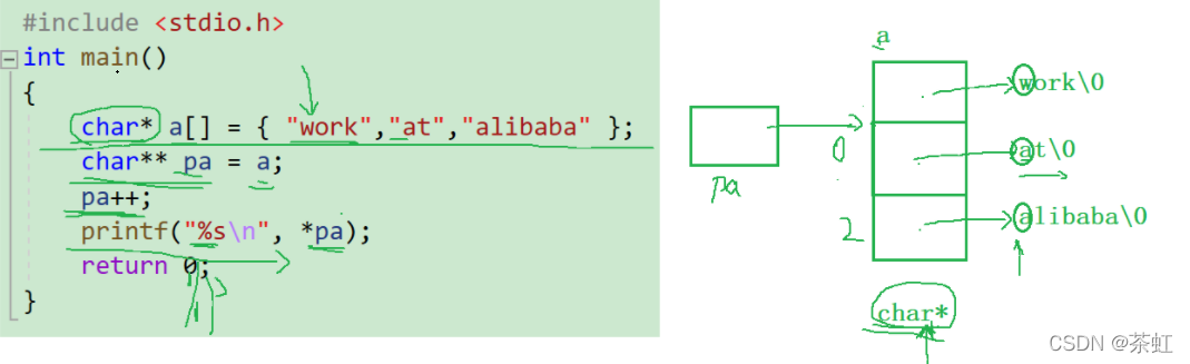
C language --- advanced pointer
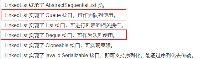
一刷314-剑指 Offer 09. 用两个栈实现队列(e)
Tencent offer has been taken. Don't miss the 99 algorithm high-frequency interview questions. 80% of them are lost in the algorithm
5分钟,把你的Excel变成在线数据库,神奇的魔方网表excel数据库

API IX JWT auth plug-in has an error. Risk announcement of information disclosure in response (cve-2022-29266)

糖尿病眼底病变综述概要记录
【现代电子装联期末复习要点】
How important is the operation and maintenance process? I heard it can save 2 million a year?
随机推荐
dlopen/dlsym/dlclose的简单用法
js正則判斷域名或者IP的端口路徑是否正確
Do we media make money now? After reading this article, you will understand
Read the meaning of serial port and various level signals
MySQL - MySQL查询语句的执行过程
建设星际计算网络的愿景
JVM - Chapter 2 - class loader subsystem
Implement default page
Upgrade MySQL 5.1 to 5.69
shell脚本中的DATE日期计算
Upgrade MySQL 5.1 to 5.68
TIA博图——基本操作
Upgrade MySQL 5.1 to 5.611
s16. One click installation of containerd script based on image warehouse
Neodynamic Barcode Professional for WPF V11. 0
Unity shader learning
MySQL optimistic lock to solve concurrency conflict
腾讯Offer已拿,这99道算法高频面试题别漏了,80%都败在算法上
Spark 算子之coalesce与repartition
Upgrade MySQL 5.1 to 5.610