当前位置:网站首页>FOC SVPWM function pwmc_ Setphasevoltage parsing
FOC SVPWM function pwmc_ Setphasevoltage parsing
2022-04-23 06:47:00 【tilblackout】
One 、 Sector judgment
wUAlpha = Valfa_beta.qV_Component1 * ( int32_t )pHandle->hT_Sqrt3;//hT_Sqrt3 by 2/√3
wUBeta = -( Valfa_beta.qV_Component2 * ( int32_t )( pHandle->hPWMperiod ) ) * 2;
wX = wUBeta;
wY = ( wUBeta + wUAlpha ) / 2;
wZ = ( wUBeta - wUAlpha ) / 2;
ST The official sector is as follows :

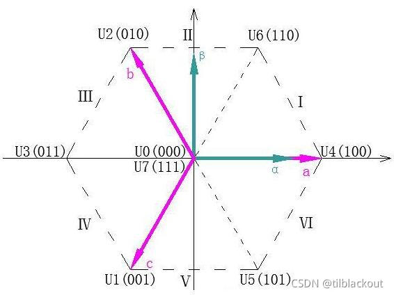
By way of anti Park Transform to get vector  and
and  , First of all, we need to know which sector the combined vector is in . Take the vector to be synthesized in the first sector as an example , When
  And
And  when , The vector may be in I or II A sector , Demand only tan The angle can determine which sector the synthesized vector is in .

Finally, the rules are summarized as follows :

It can be known from the above table , Judge 、 、
、 And 0 The size relationship of , Then calculate the three-phase duty cycle according to this variable , So this is multiplied by the period T.


1、wY<0: namely  , The target vector is 3、4、5 A sector
(1)wZ<0, Then in sector 5
(2)wZ≥0:①wX≤0 when , In sector 4 ②wX>0 when , Then in sector 3
2、wY>0: namely  , The target vector is 1、2、6 A sector
(1)wZ≥0, Then in sector 2
(2)wZ<0:①wX≤0 when , In sector 6 ②wX>0 when , Then in sector 1
Two 、 Vector time calculation
Here, take the first sector as an example to explain .
(1) First, it is necessary to ensure that the vector synthesized by adjacent vectors is within the boundary of regular hexagon , Otherwise, the voltage output waveform of the inverter will be distorted .

The amplitude of the basic space vector , That is, the value of phase voltage , The size is  , When the action time of non-zero vector is 0 when , The synthetic vector size of adjacent basic space vectors is
  . Divide the two , That is, the amplitude of the basic space vector after normalization :
 .
.
(2) The next step is to calculate the vector action time


 (ST The official benchmark is the fourth quadrant , So there's a minus sign )

Finally, we can find :
 ,
, 
Find out  ,
, , And zero vector action time
  .
.
Next, analyze the duty cycle in the code :
The seven segment formula of the first sector SVPWM The wave generation order is :0-4-6-7-6-4-0

Now we ask for A、B、C Three phase CCR value wTimePhA、 wTimePhB and wTimePhC, and TIM Set to center alignment mode , In the end, we can get :


- Similarly, the seven segment formula of other sectors can be obtained SVPWM Duty cycle and wave waveform of :
- In the table tA、tB、tC Indicates the entire high level time , and CCR Values are different .

- Why different sectors A、B、C The waveforms of the phases are different ?
First, let's look at the definition of six sectors , This is not by 0~6 In sequence , Instead, it ensures that there is only one bit difference between two adjacent sectors , This can reduce MOSFET The number of switches .
Finally, it can be concluded that different sectors have the following switching order , Drawn in binary, it corresponds to different sectors in front of SVPWM 7 Segment diagram
| A sector | Seven paragraphs SVPWM The order |
| I | 0-4-6-7-7-6-4-0 |
| II | 0-2-6-7-7-6-2-0 |
| III | 0-2-3-7-7-3-2-0 |
| IV | 0-1-3-7-7-3-1-0 |
| V | 0-1-5-7-7-5-1-0 |
| VI | 0-4-5-7-7-5-4-0 |
Finally, take the first sector as an example , Analysis related configuration codes :
static void MX_TIM1_Init(void)
    TIM_InitStruct.CounterMode = LL_TIM_COUNTERMODE_CENTER_UP;
    TIM_InitStruct.Autoreload = ((PWM_PERIOD_CYCLES) / 2);

uint16_t PWMC_SetPhaseVoltage( PWMC_Handle_t * pHandle, Volt_Components Valfa_beta )
    pHandle->hSector = SECTOR_1;
    wTimePhA = ( int32_t )( pHandle->PWMperiod ) / 4 + ( ( wX - wZ ) / ( int32_t )262144 );
    wTimePhB = wTimePhA + wZ / 131072;
    wTimePhC = wTimePhB - wX / 131072;
    pHandle->hCntPhA = ( uint16_t )wTimePhA;
    pHandle->hCntPhB = ( uint16_t )wTimePhB;
    pHandle->hCntPhC = ( uint16_t )wTimePhC;
    pSetADCSamplingPoint = pHandle->pFctSetADCSampPointSect1;
    return ( pSetADCSamplingPoint( pHandle ) );

static uint16_t R3_1_F30X_WriteTIMRegisters( PWMC_Handle_t * pHdl )
    TIMx->CCR1 = pHandle->_Super.hCntPhA;
    TIMx->CCR2 = pHandle->_Super.hCntPhB;
    TIMx->CCR3 = pHandle->_Super.hCntPhC;
(1)CCR Directly equal to hCntPhA、hCntPhB、hCntPhC
From the top seven paragraphs SVPWM As can be seen from the picture of ,a、b、c Three phase PWM The waveform is centrally aligned :
In count up or count down mode ,PWM The period is equal to ARR; In the center alignment mode ,PWM The period is equal to 2ARR.
Here, the counting order of the central alignment mode is from ARR~0~ARR, Instead of 0~ARR~0:
① from ARR Reduced to CRR: Low level
② from CCR Reduced to 0: High level
③ from 0 Add to CCR: High level
④ from CCR Add to ARR: Low level
(2)hPWMperiod and T
hPWMperiod = T. In center alignment mode PWM The period is 2 times ARR, therefore TIM_ARR Set up in order to hPWMperiod/2. And we calculated earlier T4 and T6 When , Used in the formula T It represents a whole cycle of T.
(3)131072 and 262144
We calculated earlier that wTimephA、wTimephB、wTimephC, as follows :
because ADC The collected current is left aligned , So it is  Format , Calculation PWM When comparing values, change to
  Format , So the calculation here needs to move to the right first 15 position , namely
  . Plus wUAlpha and wUBeta The definition is multiplied by one more 2, therefore X、Z And divide by one more 2.
in addition  、
、 , So I'll change the division in the code to shift right 17 Bit and 18 position , So as to speed up the operation .
版权声明
本文为[tilblackout]所创,转载请带上原文链接,感谢
https://yzsam.com/2022/04/202204230549282825.html
边栏推荐
猜你喜欢


随机推荐
The use of volatile in C language
C [document operation] PDF files and pictures are converted to each other
获取当前一周的时间范围
深蓝学院激光slam理论与实践 -第二章(里程计标定)作业
在visual stdio中运行qt程序
FOC 单电阻采样 位置环控制伺服电机
JS高频面试题
Interprocess communication - mutex
2022ldu winter vacation training - program patch
Assembler 32-bit unsigned addition calculator
cartographer_node 编译没问题,但是运行直接挂掉的bug
汇编 32位无符号加法计算器
欢迎使用Markdown编辑器
CUDA project encountered a series of compilation problems after changing the environment (computer)
CUDA环境安装
ES6
约瑟夫序列 线段树 O(nlogn)
[UDS unified diagnosis service] IV. typical diagnosis service (3) - read fault information function unit (storage data transmission function unit)
[stepping on the pit] MELD in win11 wsl2 cannot be used normally. Problem repair
导入文件时候 new FormData()