当前位置:网站首页>CANopen usage method and main parameters of object dictionary
CANopen usage method and main parameters of object dictionary
2022-04-23 18:22:00 【Things will turn when they reach the extreme 1024】
Main parameter configuration of object dictionary
0x1000-0x1029 system parameter
0x1005 SYNC CON ID involve CANopen The host sent SYNC Sync frame ID And enable
0x1005 Sub indicators 0x00 Value :
31: meaningless
30:gen 0: Do not generate synchronization messages 1: Generate synchronization message
29:frame 0 11 position CAN-ID It works 1 29 position CAN-ID It works
28:0 ID 0:10 11 position ID 0:28 29 position ID
Generally, the host is defined as 0x40000080 Send synchronization message ,11 position ID,ID=0x80.
0x1006 Definition SYNC Time interval of
namely SYNC Cycle unit of transmission ms 0 Then disable SYNC 1000 be 1S Send a synchronization frame
0x1007 SYNC Synchronization window
Indicates that the host is sending SYNC How long after receiving the synchronization message is valid , It doesn't work for the time being
0x1016 The host detects the heartbeat timeout of the slave
The type of setting value is 32 Bit , front 16 Bit represents slave ID Number , after 16 Bit is the inspection time .0x107D0 The detection time of slave I is 0x07d0 That is to say 2S.
0x1017 The heartbeat interval sent by the slave
0x1400-0x15FF To configure PDO receive
This has no effect for the time being
0x1600-0x17FF
PDO Receive mapping address , example 0x1600 After clicking, you can right-click the sub indicator to add a sub indicator , Sub indicators 0x00 instructions PDOx How many addresses are mapped , except 0x00 Sub indicators other than , The optional value is 0x2000-0x5FFF Region defined scalar , After the configuration of this area is completed, you can use a shorter PDO Instruction to change the value of the mapping address . Try to configure this in the dictionary , Don't use... In operation PDO Change the agreement .
example :0x1403 0x01=DI+0x500;0x1603 0x00=1;0x01=0x2003;ID=0x03;
Then send ID=0x503 data=06 05 03 04 The end result is 0x2003 The value of is updated according to its own data type , if u8 type , It becomes 0x06,u32 Type changed to 0x04030506.
0x1403 0x01=DI+0x500;0x1603 0x00=2;0x01=0x2003;0x02=0x2004;ID=0x03;
Then send ID=0x503 data=06 05 03 04 0x2003 and 0x2004 by u16 type , 0x2003=0x0506,0x2004=0x0403.
Be careful ID Format PDO Different areas of ,data There is no requirement , however ID Different will correspond directly to different PDO Area .
There are errors in the above data ,0x1600-0x17FF and 0x1A00-0x1BFF yes PDO Mapping , Two of his four data are mapping relationships ( The variable corresponding to the object dictionary ), One is the data type of mapping relationship , One is the sub index of the mapping relationship .
example : value 20000108 h For mapping to index 2000h Sub index of 01h, The object is 8 position From left to right 2000 Is a mapping relationship 01 It's a sub index ,08 Represents the data type
The above example , use SDO The instruction is written as 23 01 00 16 08 01 00 20, Please refer to PDO Use and routine configuration corresponding variables
data type
| 0x08 | 8 position |
| 0x10 | 16 position |
| 0x20 | 32 position |
0x1A00-0x1BFF
This area and 0x1600-0x17FF Usage is similar. , Difference is that 0x1600-0x17FF Is to receive the number from outside ,0x1A00-0x1BFF The number of sent itself , The data to be sent directly corresponds to the mapping address .
0x1800-0x19FF PDO Communication parameters
This area is focused on understanding . With 0x1800 For example , Sub indicators are generally seven
0x00 : Number of sub indicators
0x01 :ID 0x180+ Fix
0x02 :Transmission type Send type
00h: Acyclic synchronization
Can only send asynchronously ( That is, receiving the sending request or actively sending ), Received SYNC Frames will not be sent .
01h-FBh: Cyclic synchronization
according to TestSlave_obj1400_SYNC_start_value The value set inside receives SYNC Send the number of once .
FCh: Remote synchronization
When I received PDO request , If so PDO_status Status bit of PDO_RTR_SYNC_READY Set up ( You'll receive SYNC Signal call _sendPDOevent in BuildPDO Juxtapose this bit ), Then directly send PDO The last frame of .
FDh: Remote asynchronous
When I received PDO request (SendPDORequest) Immediately after BuildPDO Send the requested PDO frame (cob_id Mark ).
FEh: asynchronous , Manufacturer specific events and FFh: asynchronous , Device sub protocol specific events
call sendPDOevent()( Not blocked inhibited) Post establishment PDO And check it PDO Frame is the same as the last transmission (PDO_status.last_message) Of PDO Whether the frame content changes , If there is a change, send , Otherwise do not send . Received SYNC Frame will not be sent . But if you receive PDO The request is forced to establish and send .
0x03:Inhibit Time PDO Minimum period of transmission Set up as 1S, be 1S Send at most once in , The rest will not be executed , The transmission frequency when the limit value changes .0x00 Don't take effect
0x04:Compatibility Entry Temporarily useless
0x05:Event Time Time to send , if 0x03=0xFE or 0xFF, stay Canopen In the operating state , Send regularly according to the specified time of this variable :1000=1S.0x00 Send from time to time .
0x06: Synchronous transmission PDO, After receiving a synchronization package from Nuo , Before sending This doesn't work .
0x2000-0x5FFF User defined area
User configurable area , Generally, it is blank after creating a new one , You can add map variables :
indicators :0x2000-0x5FFF arbitrarily , This is for PDO Address mapping or SDO Direct control
name : The variable name in the program , Single chip microcomputer PDO、SDO The number sent and the number changed after receiving is the name .
type :VAR A single variable that is not extensible ;ARRAY Array ;REC Multiple variables ;ARRAY and REC When adding map variables, the number entered is the number of elements and variables of the array , Pay attention to the names of map variables and sub indicators , If the same naming program appears, an error will be reported .
0x6000-0x9FFF Standardized equipment sub protocol area
When building the object dictionary, if Profile Choice is not without , Some variables will be automatically defined in this area , It belongs to the unchangeable area , When used, it is the same as the user-defined area , It belongs to the general agreement .
SDO Use and routines
First say SDO, This is simpler , and PDO Configuration will use SDO The way
SDO write in
SDO write in ( Host send )
| Number of bytes | ID | RTR | Function code | Index_L | Index_H | Sub index | data | data | data | data |
|---|---|---|---|---|---|---|---|---|---|---|
| A byte | 600 + ServNodeId | 0 | 2F | Index_L | Index_H | Sub index | D0 | - | - | - |
| Two bytes | 600 + ServNodeId | 0 | 2B | Index_L | Index_H | Sub index | D0 | D1 | - | - |
| Three bytes | 600 + ServNodeId | 0 | 27 | Index_L | Index_H | Sub index | D0 | D1 | D2 | - |
| Four bytes | 600 + ServNodeId | 0 | 23 | Index_L | Index_H | Sub index | D0 | D1 | D2 | D3 |
SDO write in ( The host receives )
success :
| ID | RTR | Function code | Index_L | Index_H | Sub index | data | data | data | data |
|---|---|---|---|---|---|---|---|---|---|
| 580 + Serv NodeId | 0 | 60 | Index_L | Index_H | Sub index | 00 | 00 | 00 | 00 |
When the failure :
| ID | RTR | Function code | Index_L | Index_H | Sub index | data[0…3] |
|---|---|---|---|---|---|---|
| 580 + Serv NodeId | 0 | 80 | Index_L | Index_H | Sub index | SDO abort code error |
example :DI:0x621 DLC 8 Standard frame Data frame DATA:2F 01 14 02 FD 00 00 00
write in ID by 0x21 Of 0x1401, Sub indicators 0x02, The data is 0xFD
success :DI:0x5A1 DLC 8 Standard frame Data frame DATA:60 01 14 02 00 00 00 00
DI:0x621 DLC 8 Standard frame Data frame DATA:23 01 16 02 FD 65 43 21
write in ID by 0x21 Of 0x1601, Sub indicators 0x02, The data is 0x314365FD
SDO Read
SDO Read ( Host send )
| ID | RTR | Function code | Index_L | Index_H | Sub index | data | data | data | data |
|---|---|---|---|---|---|---|---|---|---|
| 600 + Serv NodeId | 0 | 40 | Index_L | Index_H | Sub index | 00 | 00 | 00 | 00 |
SDO Read ( The host receives )
success :
| Number of bytes | ID | RTR | Function code | Index_L | Index_H | Sub index | data | data | data | data |
|---|---|---|---|---|---|---|---|---|---|---|
| A byte | 580 + ServNodeId | 0 | 4F | Index_L | Index_H | Sub index | D0 | - | - | - |
| Two bytes | 580 + ServNodeId | 0 | 4B | Index_L | Index_H | Sub index | D0 | D1 | - | - |
| Three bytes | 580 + ServNodeId | 0 | 47 | Index_L | Index_H | Sub index | D0 | D1 | D2 | - |
| Four bytes | 580 + ServNodeId | 0 | 43 | Index_L | Index_H | Sub index | D0 | D1 | D2 | D3 |
Failure
| ID | RTR | Function code | Index_L | Index_H | Sub index | data[0…3] |
|---|---|---|---|---|---|---|
| 580+ Serv NodeId | 0 | 8 | Index_L | Index_H | Sub index | SDO abort code error |
example :DI:0x621 DLC 8 Standard frame Data frame DATA:40 01 14 02 00 00 00 00
Read ID by 0x21 Of 0x1401, Sub indicators 0x02
success :DI:0x5A1 DLC 8 Standard frame Data frame DATA:60 01 14 02 FD 00 00 00
The value read is 0xFD
DI:0x621 DLC 8 Standard frame Data frame DATA:40 01 16 02 00 00 00 00
success :DI:0x5A1 DLC 8 Standard frame Data frame DATA:60 01 14 02 FD 65 43 21
The data read is 0x214365FD
PDO Use and routines
PDO The default is 4 Four sending areas and four receiving areas , To configure PDO This is the configuration 4R4T Corresponding program variables , And this 4R4T Working mode of .
Configure the corresponding variable
The first method is to match... Directly in the object dictionary
Method 2: configure... In the program , Use SDO Change the way Mapping(0x1A00-0x1BFF and 0x1600-0x17FF) The value of the inside
example :
605 2F 00 18 02 FF 00 00 00 -- catalog index Index 1800, Event transport
605 2F 00 18 05 CB 00 00 00 -- catalog index Index 1800, The time interval 200ms
605 2F 00 1A 00 00 00 00 00 -- Set sub index to disable
605 23 00 1A 01 10 00 30 40 --0x40300010, Set mapping index 0x4030, Subindex 00, size 0x10(16 position )
605 23 00 1A 02 20 00 10 20 --0x20100020, Set mapping index 0x2010, Subindex 00, size 0x20(32 position )
605 2F 00 1A 00 02 00 00 00 -- Set the number of mappings , Set as many as you use , This is used here. 01–02
Be careful : When defining a mapping , First set the sub index to disable ; Then set the corresponding mapping ; Then set the number of mappings
example :
ID=0x700+ID,rtr=1( Remote frame ) Request node status
DI=0x00,rtr=0,DLC=2,Data[0]=0x01(Start),Data[1]= Specify the device address , All are 0. Set nodes start
DI=0x00,rtr=0,DLC=2,Data[0]=0x02(Stop),Data[1]= Specify the device address , All are 0. Set nodes Stop
DI=0x180+ID,RTR=0 PDOTX1 Remote control frame
DI=0x280+ID,RTR=0 PDOTX2 Remote control frame
data type
| 0x08 | 8 position |
| 0x10 | 16 position |
| 0x20 | 32 position |
Configure working mode
Configuration 0x1400-0x19FF and 0x1800-0x19FF,0x1400-0x19FF Area management MCU receives , I don't see this effect at present . Use words similar to sending , May refer to 0x1800-0x19FF District .
The last chapter has already introduced 0x1800-0x19FF Parameters , The main configuration is 0x01,0x05.0x03 It's usually fixed .
example :
605 2F 00 18 02 FF 00 00 00 -- catalog index Index 1800, Event transport
605 2F 00 18 05 CB 00 00 00 -- catalog index Index 1800, The time interval 200ms
605 2F 00 1A 00 00 00 00 00 -- Set sub index to disable
605 23 00 1A 01 10 00 30 40 --0x40300010, Set mapping index 0x4030, Subindex 00, size 0x10(16 position )
605 23 00 1A 02 20 00 10 20 --0x20100020, Set mapping index 0x2010, Subindex 00, size 0x20(32 position )
605 2F 00 1A 00 02 00 00 00 -- Set the number of mappings , Set as many as you use , This is used here. 01–02
After the above configuration is completed, data can be sent directly
0x180+id data ( No function code , All valid ) 12 34 56 78 9A 00 be 0x4030=0x3412 0x2010=0x009A7856
Function callback
1、 Check "return visit" in the object dictionary
2、 Define callback function
typedef UNS32 (*ODCallback_t)(CO_Data* d, const indextable *, UNS8 bSubindex);
 example :
/* index 0x2000 : Mapped variable value */
UNS32 index2000_callback(CO_Data* d, const indextable *table, UNS8 bSubindex)
{

	printf("value=%x\r\n",*(uint8_t*)table->pSubindex[bSubindex].pObject);
	return OD_SUCCESSFUL;
}
3、 Callback function access
The first is to assign values directly in the dictionary :
/* index 0x2000 : Mapped variable value */
  subindex slave_objdict_Index2000[] =
   {

     {
     RW, uint8, sizeof (UNS8), (void*)&value, index2000_callback }
   };
The second is to call UNS32 RegisterSetODentryCallBack(CO_Data* d, UNS16 wIndex, UNS8 bSubindex, ODCallback_t Callback) This function :
RegisterSetODentryCallBack(&slave_objdict_Data,0x2000, 0, index2000_callback);
Special callback function : The master detects that the slave is lost
void _heartbeatError(CO_Data* d, UNS8 heartbeatID){
    heartbeat_error(d,heartbeatID);}
//d by CO_Data ,heartbeatID For slave ID value .
// function _heartbeatError be located lifegrd file , The original function is void _heartbeatError(CO_Data* d, UNS8 heartbeatID){(void)d;(void)heartbeatID;}
// Change it to void _heartbeatError(CO_Data* d, UNS8 heartbeatID){heartbeat_error(d,heartbeatID);}
// Talk about adding the header file where the function you wrote is located lifegrd, Introduction statement
// Write the function body
void heartbeat_error(CO_Data* d, UNS8 heartbeatID)
{

	printf("heartbeatID %d\r\n",heartbeatID);
}
// Statement
void heartbeat_error(CO_Data* d, UNS8 heartbeatID);
// About index 0x1016
// front 16 Bit represents slave ID Number , after 16 Bit is the inspection time  20000+(0x02<<16) ID 0x02 Timeout time 20000ms=20s
// The start time is... Received ID 0x700+ID +data data=0x00, namely Boot up State start
Address is function
Reference resources CANOpen-memento file
CAN frame ID 11 position
COB-ID Eleven
Node-ID: node , ID The last seven
ID The no. 10-7 Senior four , Hereinafter referred to as the function code ID The last seven digits of the number are 0, Only the top four
1、0x700+Node-ID NMT Error Control
It's feedback CANopen System status , That is, heartbeat frame
Function code =0x700,ID=0x700+Node-ID length DLC=1
Data : 00 Node online message (boot-up)
04 h It is in the stop state stop
05 h The operation status is operational
7F h It is in pre operation state pre-operational
2、0x80 Sync frame
ID Fixed for 0x80 DLC=0; Only on PDO It works
3、PDO Remote control frame
Remote frame ,DLC Constant is 0,ID Combined with the function code, it directly affects the slave , When slave PDO Map There are sending types >=FC Of , Will correspond to .
0x180+Node-ID PDO1 send out
0x200+Node-ID PDO1 receive
0x280+Node-ID PDO2 send out
0x300+Node-ID PDO2 receive
0x380+Node-ID PDO3 send out
0x400+Node-ID PDO3 receive
0x480+Node-ID PDO4 send out
0x500+Node-ID PDO4 receive
4、PDO
Address with PDO Remote control frame , The frame format shall be data frame , namely DLC and Data meaningful , This is being configured PDO map after , This frame format sent by the right MCU and the received frame format ,Data All valid data .
0x180+Node-ID PDO1 send out
0x200+Node-ID PDO1 receive
0x280+Node-ID PDO2 send out
0x300+Node-ID PDO2 receive
0x380+Node-ID PDO3 send out
0x400+Node-ID PDO3 receive
0x480+Node-ID PDO4 send out
0x500+Node-ID PDO4 receive
5、0x00 NMT Network management command
NMT Module Control
ID Constant 0x00
DLC=1 Time broadcast DLC=2 When broadcasting, you can specify
Data[0]:
0x01 operational Pattern Operation mode ( Normal operation mode )
0x02 stop Pattern ( silent )
0x80 pre-operational Pattern ( wait for )
0x81 reset-application Pattern ( Reset )
0x82 reset-communication Pattern ( Reset )
Data[1]: Node-ID The status of other devices in the network changes to Data[0] Specified state
example :DLC=2 Data: 0x02 0x55 node 0x55 Change to stop
6、SDO 0x600+Node-ID and 0x580+Node-ID
Whether sent by MCU or others to MCU , That is, whether the master or slave , Whether sending or reading .
Send send instruction or send read instruction :ID=0x600+Node-ID
Send instruction return or read instruction return :ID=0x580+Node-ID
Reference resources SDO Use and routines
CAN filter
1、 Configure the filter so that the filter group works in initialization mode , Enter normal mode after configuration
CAN1->FMR|=1<<0;		// Filter bank 0 Working in initialization mode
//CAN1->FMR|=1<<n; // Filter bank n Working in initialization mode
/*... To configure */
CAN1->FMR&=0<<0;		// Filter bank 0 Enter normal mode
//CAN1->FMR&=0<<n; // Filter bank n Enter normal mode
2、 When configuring a filter, it is also necessary to turn off the activation of the filter
CAN1->FA1R&=~(1<<0);	// filter 0 Do not activate
//CAN1->FA1R&=~(1<<n); // filter n Do not activate

CAN1->FA1R|=1<<0;		// Activate the filter 0
//CAN1->FA1R|=1<<n; // Activate the filter n
3、 Set the filter bit width , Yes 32 Bit and 16 Two modes , This affects the later filtering and shielding ID length
CAN1->FS1R|=1<<0; 		// filter 0 The seat width is 32 position
CAN1->FS1R&=~(1<<0); 		// filter 0 The seat width is 16 position
CAN1->FS1R|=1<<n; 		// filter n The seat width is 32 position
CAN1->FS1R&=~(1<<n); 		// filter n The seat width is 16 position
STID standard ID
EXID Expand ID
IDE
RTR
32 Bit mode
| CAN_FxR1[31:21] | CAN_FxR1[20:3] | CAN_FxR1[2] | CAN_FxR1[1] | CAN_FxR1[0] |
|---|---|---|---|---|
| CAN_FxR2[31:21] | CAN_FxR2[20:3] | CAN_FxR2[2] | CAN_FxR2[1] | CAN_FxR2[0] |
| STID[10:0] | EXID[17:0] | IDE | RTR | 0 |
16 Bit mode
| CAN_FxR1[15:5] | CAN_FxR1[4] | CAN_FxR1[3] | CAN_FxR1[2:0] |
|---|---|---|---|
| CAN_FxR1[31:21] | CAN_FxR1[20] | CAN_FxR1[19] | CAN_FxR1[18:16] |
| CAN_FxR2[15:5] | CAN_FxR2[4] | CAN_FxR2[3] | CAN_FxR2[2:0] |
| CAN_FxR2[31:21] | CAN_FxR2[20] | CAN_FxR2[19] | CAN_FxR2[18:16] |
| STID[10:0] | IDE | RTR | EXID[17:15] |
4、 Set the filter operating mode , Identifier mask bit mode and identifier list mode
CAN1->FM1R&=~(1<<0);		// filter 0 Working in identifier mask bit mode
CAN1->FM1R|=1<<0;		// filter 0 Working in identifier list mode
CAN1->FM1R&=~(1<<n);		// filter n Working in identifier mask bit mode
CAN1->FM1R|=1<<n;		// filter n Working in identifier list mode
5、 Filter associated to FIFOn n=0,1
CAN1->FFA1R&=~(1<<0); // filter 0 Related to FIFO0CAN1->FFA1R|=1<<0; // filter 0 Related to FIFO1CAN1->FFA1R&=~(1<<n); // filter n Related to FIFO0CAN1->FFA1R|=1<<n; // filter n Related to FIFO1
6、 Set filtering rules
CAN1->sFilterRegister[0].FR1=0x21<<21;//32 position ID CAN1->sFilterRegister[0].FR2=(0x7F<<21);//32 position MASK
Identifier pattern
Each of the registers corresponds to the level of the corresponding bit of the desired identifier .
0: It is expected that the corresponding bit is dominant ;
1: The corresponding bit is expected to be recessive .
Mask bit mode
Each bit of the register indicating whether the corresponding identifier register bit must be consistent with the corresponding bit of the desired identifier .
0: No concern , This bit is not used for comparison ;
1: Must match , The incoming identifier bit must be consistent with the identifier register bit corresponding to the filter
The identifier pattern is FR2 by 1 The bit of identifies the bit to be verified ,FR1 Explain what the identified bit must be , That is, a filter, a rule , The logic here is similar to & operation
CAN1->sFilterRegister[0].FR1=0x21<<21;//32 position ID CAN1->sFilterRegister[0].FR2=(0x7F<<21);//32 position MASK// Means to check SDID Standard frame ID The lower seven of , The lower seven must be 0x21 To pass
Mask bit mode Is to specify a specific one ID,ID All bits of must conform to the set value
CAN1->sFilterRegister[0].FR1=0x21<<21;//32 position IDCAN1->sFilterRegister[0].FR2=0xFF<<21)//32 position MASK// Only 0x00 and 0xFF It can be filtered
Program routine
void CAN_Set_Filter(u8 Addr){
    	Addr=Addr&0x7F;	// Filter initialization  CAN1->FMR|=1<<0; // The filter group works in initialization mode /* Filtering rules 1 CAN ID The lower seven digits of must be the same as Addr Agreement , Others don't care  */ CAN1->FA1R&=~(1<<0); // filter 0 Do not activate  CAN1->FS1R|=1<<0; // The filter bit width is 32 position . CAN1->FM1R|=0<<0; // filter 0 Working in identifier mask bit mode  //CAN1->FM1R|=1<<0; // filter 0 Working in identifier list mode  CAN1->FFA1R|=0<<0; // filter 0 Related to FIFO0 CAN1->sFilterRegister[0].FR1=Addr<<21;//32 position ID CAN1->sFilterRegister[0].FR2=(0x7F<<21);//32 position MASK CAN1->FA1R|=1<<0; // Activate the filter 0/* Filtering rules 2 CAN ID Of the 7 Bit must be 1, That is, only 0x80 Can pass */ CAN1->FA1R&=~(1<<1); // filter 1 Do not activate  CAN1->FS1R|=1<<1; // filter 1 The seat width is 32 position . CAN1->FM1R|=0<<1; // filter 1 Working in identifier mask bit mode  //CAN1->FM1R|=1<<1; // filter 1 Working in identifier list mode  CAN1->FFA1R|=0<<1; // filter 1 Related to FIFO0 CAN1->sFilterRegister[1].FR1=0x80<<21;//32 position ID CAN1->sFilterRegister[1].FR2=(0x80<<21);//32 position MASK CAN1->FA1R|=1<<1; // Activate the filter 1/* Filtering rules 3 CAN ID The lower eight digits of must be 0x00*/ CAN1->FA1R&=~(1<<2); // filter 2 Do not activate  CAN1->FS1R|=1<<2; // filter 2 The seat width is 32 position . CAN1->FM1R|=0<<2; // filter 2 Working in identifier mask bit mode  //CAN1->FM1R|=1<<2; // filter 2 Working in identifier list mode  CAN1->FFA1R|=0<<2; // filter 2 Related to FIFO0 CAN1->sFilterRegister[2].FR1=0x00<<21;//32 position ID CAN1->sFilterRegister[2].FR2=(0xFF<<21);//32 position MASK CAN1->FA1R|=1<<2; // Activate the filter 2 CAN1->FMR&=0<<0; // The filter bank enters normal mode }
版权声明
本文为[Things will turn when they reach the extreme 1024]所创,转载请带上原文链接,感谢
https://yzsam.com/2022/04/202204210610057146.html
边栏推荐
- QT notes on qmap container freeing memory
- Robocode tutorial 8 - advanced robot
- Dynamically add default fusing rules to feign client based on sentinel + Nacos
- CISSP certified daily knowledge points (April 15, 2022)
- Install pyshp Library
- Daily network security certification test questions (April 18, 2022)
- mysql自动启动设置用Systemctl start mysqld启动
- 解决允许在postman中写入注释请求接口方法
- Function recursion and solving interesting problems
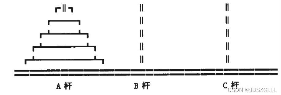
- Queue solving Joseph problem
猜你喜欢
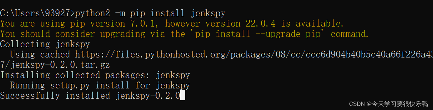
Jenkspy package installation
函数递归以及趣味问题的解决
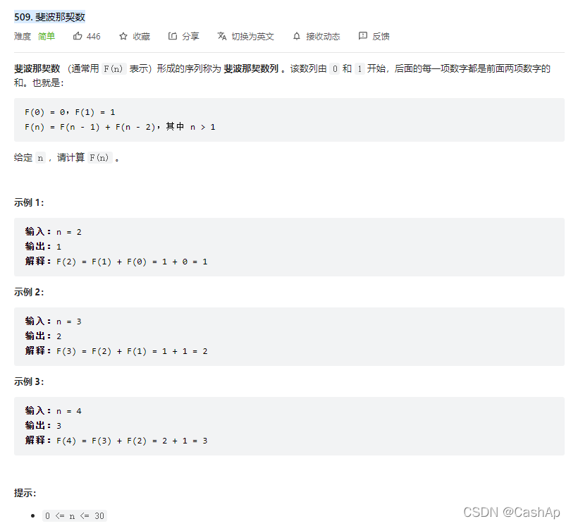
【ACM】509. 斐波那契数(dp五部曲)
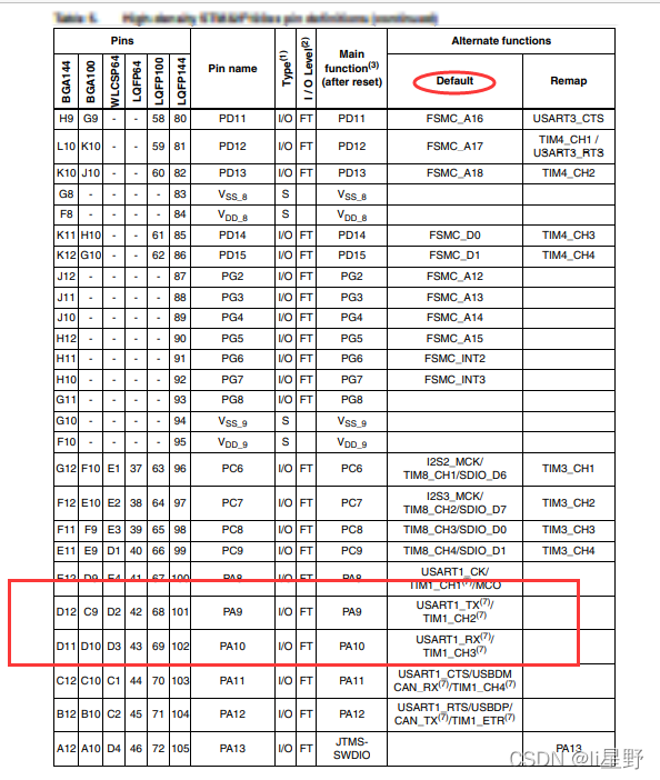
STM32 learning record 0008 - GPIO things 1
Custom prompt box MessageBox in QT
Installation du docker redis
Imx6 debugging LVDS screen technical notes
![解决报错max virtual memory areas vm.max_map_count [65530] is too low, increase to at least [262144]](/img/5f/a80951777a0473fcaa685cd6a8e5dd.png)
解决报错max virtual memory areas vm.max_map_count [65530] is too low, increase to at least [262144]

Hard core parsing promise object (do you know these seven common APIs and seven key questions?)
Win1远程出现“这可能是由于credssp加密oracle修正”解决办法
随机推荐
Differences between SSD hard disk SATA interface and m.2 interface (detailed summary)
mysql自动启动设置用Systemctl start mysqld启动
With the use of qchart, the final UI interface can be realized. The control of qweight can be added and promoted to a user-defined class. Only the class needs to be promoted to realize the coordinate
Halo 开源项目学习(七):缓存机制
Daily CISSP certification common mistakes (April 19, 2022)
CISSP certified daily knowledge points (April 19, 2022)
登录和发布文章功能测试
由tcl脚本生成板子对应的vivado工程
From introduction to mastery of MATLAB (2)
Cutting permission of logrotate file
Rust: the output information of println is displayed during the unit test
In shell programming, the shell file with relative path is referenced
GDAL + ogr learning
Rust: a simple example of TCP server and client
Pyppeter crawler
Connection mode of QT signal and slot connect() and the return value of emit
idea中安装YapiUpload 插件将api接口上传到yapi文档上
【ACM】509. Fibonacci number (DP Trilogy)
Jenkspy package installation
Daily network security certification test questions (April 13, 2022)