当前位置:网站首页>【Gazebo入门教程】第三讲 SDF文件的静/动态编程建模
【Gazebo入门教程】第三讲 SDF文件的静/动态编程建模
2022-08-10 13:35:00 【生如昭诩】
【Gazebo入门教程】第三讲 SDF文件的静/动态编程建模

文章目录
一、自定义模型并导入Gazebo
- 内容简介:本节内容以一个两轮移动机器人为例,使用差动驱动机构运动,从无到有,使用SDF完成建模并在Gazebo中完成仿真,重点在于通过建模的细致流程掌握如何使用SDF文件和Gazebo软件完成机器人仿真。
1. 基础操作准备
- 注意:Gazebo的模型文件有着严格的要求,具体规则可见SDF格式
\qquad ① 创建模型目录
mkdir -p ~/.gazebo/models/my_robot
\qquad ② 创建模型配置文件
gedit ~/.gazebo/models/my_robot/model.config
\qquad 元数据(config)内容如下:
	<?xml version="1.0"?>
	<model>
	  <name>My Robot</name>
	  <version>1.0</version>
	  <sdf version='1.4'>model.sdf</sdf>

	  <author>
	   <name>My Name</name>
	   <email>[email protected]</email>
	  </author>

	  <description>
	    My awesome robot.
	  </description>
	</model>
\qquad ② 创建模型配置文件
gedit ~/.gazebo/models/my_robot/model.sdf
\qquad 必要标记(sdf)内容如下:
	<?xml version='1.0'?>
	<sdf version='1.4'>
	  <model name="my_robot">
	  </model>
	</sdf>
2. 建立模型基础部件(静态)
- 基本要求:本节内容主要是单独创建机器人的各部件,例如底座、轮子等,不涉及相关关节连杆等链接内容,重点在于对齐组件,故模型为静态,忽略物理效果。
\qquad ① 令机器人模型静态
注意:在static标签后将会在link标签下生成对应部件,通过collision的name隔开,故在后代码展示中则会忽略一部分,请自行补充
	<?xml version='1.0'?>
	<sdf version='1.4'>
	  <model name="my_robot">
	  <static>true</static>
	  </model>
	</sdf>
\qquad ② 创建长方体的底座
代码解释:
- box 标签,用于产生对应尺寸的长方体
- collision 标签,指定碰撞尺寸
- visual 标签,指定视觉尺寸,常见情况下与collision相同
<?xml version='1.0'?>
<sdf version='1.4'>
  <model name="my_robot">
  <static>true</static>
    <link name='chassis'>
      <pose>0 0 .1 0 0 0</pose>

      <collision name='collision'>
        <geometry>
          <box>
            <size>.4 .2 .1</size>
          </box>
        </geometry>
      </collision>

      <visual name='visual'>
        <geometry>
          <box>
            <size>.4 .2 .1</size>
          </box>
        </geometry>
      </visual>
    </link>
  </model>
</sdf>
\qquad ③ 创建脚轮(万向轮)
注意:脚轮固定在底座上,故二者同属一个link
<collision name='caster_collision'>
        <pose>-0.15 0 -0.05 0 0 0</pose>
        <geometry>
            <sphere>
            <radius>.05</radius>
          </sphere>
        </geometry>

        <surface>
          <friction>
            <ode>
              <mu>0</mu>
              <mu2>0</mu2>
              <slip1>1.0</slip1>
              <slip2>1.0</slip2>
            </ode>
          </friction>
        </surface>
      </collision>

      <visual name='caster_visual'>
        <pose>-0.15 0 -0.05 0 0 0</pose>
        <geometry>
          <sphere>
            <radius>.05</radius>
          </sphere>
        </geometry>
      </visual>
    </link>
\qquad ④ 创建前轮和后轮
注意:前轮和后轮分别创建了新的link
	  <link name="left_wheel">
      <pose>0.1 0.13 0.1 0 1.5707 1.5707</pose>

      <collision name="collision">
        <geometry>
          <cylinder>
            <radius>.1</radius>
            <length>.05</length>
          </cylinder>
        </geometry>
      </collision>

      <visual name="visual">
        <geometry>
          <cylinder>
            <radius>.1</radius>
            <length>.05</length>
          </cylinder>
        </geometry>
      </visual>
    </link>

    <link name="right_wheel">
      <pose>0.1 -0.13 0.1 0 1.5707 1.5707</pose>

      <collision name="collision">
        <geometry>
          <cylinder>
            <radius>.1</radius>
            <length>.05</length>
          </cylinder>
        </geometry>
      </collision>

      <visual name="visual">
        <geometry>
          <cylinder>
            <radius>.1</radius>
            <length>.05</length>
          </cylinder>
        </geometry>
      </visual>
    </link>
\qquad ⑤ 导入Gazebo可视化模型
- 使用INSERT导入对应文件夹的模型,可看到模型如下:

注意:修改SDF文件后,只需要删除原有模型重新插入就会更新模型
3. 创建关节连接部件(动态)
- 基本要求:将static设为false,为左右车轮添加铰链关节,关节绕Y轴旋转,将各车轮连接到底盘
<static>false</static>
	<joint type="revolute" name="left_wheel_hinge">
      <pose>0 0 -0.03 0 0 0</pose>
      <child>left_wheel</child>
      <parent>chassis</parent>
      <axis>
        <xyz>0 1 0</xyz>
      </axis>
    </joint>

    <joint type="revolute" name="right_wheel_hinge">
      <pose>0 0 0.03 0 0 0</pose>
      <child>right_wheel</child>
      <parent>chassis</parent>
      <axis>
        <xyz>0 1 0</xyz>
      </axis>
    </joint>
4. Gazebo基本仿真
- 基本操作:启动Gazebo,插入最新模型,打开隐藏的右面板,选择好要控制的模型,如下图给Force下的各关节力进行修改,机器人就会发生移动:

二、创建Velodyne HDL-32 LiDAR传感器
- 内容简介:本节内容以一个两轮移动机器人为例,使用差动驱动机构运动,从无到有,使用SDF完成建模并在Gazebo中完成仿真,重点在于通过建模的细致流程掌握如何使用SDF文件和Gazebo软件完成机器人仿真。
1. 创建基本世界
- 创建新的
.world文件:
gedit velodyne.world
- 创建世界的环境:地面与光线
<?xml version="1.0" ?>
<sdf version="1.5">
  <world name="default">

    <!-- A global light source -->
    <include>
      <uri>model://sun</uri>
    </include>

    <!-- A ground plane -->
    <include>
      <uri>model://ground_plane</uri>
    </include>
  </world>
</sdf>
2. 创建传感器静态模型
- 传感器基础部分2D绘图如下:

- 对应代码如下:位于< world >的内部
<model name="velodyne_hdl-32">
  <!-- Give the base link a unique name -->
  <link name="base">

    <!-- Offset the base by half the lenght of the cylinder -->
    <pose>0 0 0.029335 0 0 0</pose>
    <collision name="base_collision">
      <geometry>
        <cylinder>
          <!-- Radius and length provided by Velodyne -->
          <radius>.04267</radius>
          <length>.05867</length>
        </cylinder>
      </geometry>
    </collision>

    <!-- The visual is mostly a copy of the collision -->
    <visual name="base_visual">
      <geometry>
        <cylinder>
          <radius>.04267</radius>
          <length>.05867</length>
        </cylinder>
      </geometry>
    </visual>
  </link>

  <!-- Give the base link a unique name -->
  <link name="top">

    <!-- Vertically offset the top cylinder by the length of the bottom cylinder and half the length of this cylinder. -->
    <pose>0 0 0.095455 0 0 0</pose>
    <collision name="top_collision">
      <geometry>
        <cylinder>
          <!-- Radius and length provided by Velodyne -->
          <radius>0.04267</radius>
          <length>0.07357</length>
        </cylinder>
      </geometry>
    </collision>

    <!-- The visual is mostly a copy of the collision -->
    <visual name="top_visual">
      <geometry>
        <cylinder>
          <radius>0.04267</radius>
          <length>0.07357</length>
        </cylinder>
      </geometry>
    </visual>
  </link>
</model>
- 启动Gazebo查看模型:(先cd到文件路径下)
	cd ~/
	gazebo velodyne.world -u

- 查看碰撞属性:右键点击模型,view→Collisions

3. 添加模型惯性
- 3.1 查看当前惯性值:右键单击模型,选择View->Inertia

注意:紫色框对应关联的链接大小,此时模型没有惯性信息,故尺寸过大
- 3.2 添加惯性信息:质量设为1.3kg,添加对应质量和惯性矩阵
在< link name=“base” >块中添加以下内容:
  <link name="base">
    <pose>0 0 0.029335 0 0 0</pose>
    <inertial>
      <mass>1.2</mass>
      <inertia>
        <ixx>0.001087473</ixx>
        <iyy>0.001087473</iyy>
        <izz>0.001092437</izz>
        <ixy>0</ixy>
        <ixz>0</ixz>
        <iyz>0</iyz>
      </inertia>
    </inertial>
在< link name=“top” >块中添加以下内容:
 <link name="top">
   <pose>0 0 0.095455 0 0 0</pose>
   <inertial>
     <mass>0.1</mass>
     <inertia>
       <ixx>0.000090623</ixx>
       <iyy>0.000090623</iyy>
       <izz>0.000091036</izz>
       <ixy>0</ixy>
       <ixz>0</ixz>
       <iyz>0</iyz>
     </inertia>
   </inertial>
最终效果如下:

4. 添加关节
- 4.1 定义顶部围绕底部旋转关节,在< world >最后添加内容如下:
<!-- Each joint must have a unique name -->
<joint type="revolute" name="joint">

  <!-- Position the joint at the bottom of the top link -->
  <pose>0 0 -0.036785 0 0 0</pose>

  <!-- Use the base link as the parent of the joint -->
  <parent>base</parent>

  <!-- Use the top link as the child of the joint -->
  <child>top</child>

  <!-- The axis defines the joint's degree of freedom -->
  <axis>

    <!-- Revolve around the z-axis -->
    <xyz>0 0 1</xyz>

    <!-- Limit refers to the range of motion of the joint -->
    <limit>

      <!-- Use a very large number to indicate a continuous revolution -->
      <lower>-10000000000000000</lower>
      <upper>10000000000000000</upper>
    </limit>
  </axis>
</joint>
- 4.2 检验效果:
1. 启动Gazebo,右键单击模型,选择View->Joints,View->Transparent

2. 打开右面板,选择Velodyne模型。使用Force选项卡向关节施加较小的,可看到关节旋转即可

5. 添加传感器
- 传感器基本信息:
激光传感器,可以发出一个或多个光束,光束产生距离和强度数据,对应SDF文件中的< scan >和< range >,分别对应波束的布局、数量和限定束的性质,其中< scan >中包含< horizontal >和< vertical >两个块。< horizontal >组件定义在水平平面中发出的光线,该< vertical >组件定义在垂直平面中发出的光线,Velodyne传感器需要垂直射线,然后旋转。我们将其模拟为旋转的水平扇面。
- 添加并设置传感器:(在的最后部分添加以下内容)
<!-- Add a ray sensor, and give it a name -->
<sensor type="ray" name="sensor">

  <!-- Position the ray sensor based on the specification. Also rotate it by 90 degrees around the X-axis so that the <horizontal> rays become vertical -->
  <pose>0 0 -0.004645 1.5707 0 0</pose>

  <!-- Enable visualization to see the rays in the GUI -->
  <visualize>true</visualize>

  <!-- Set the update rate of the sensor -->
  <update_rate>30</update_rate>
  <ray>

  <!-- The scan element contains the horizontal and vertical beams. We are leaving out the vertical beams for this tutorial. -->
  <scan>

    <!-- The horizontal beams -->
    <horizontal>
      <!-- The velodyne has 32 beams(samples) -->
      <samples>32</samples>

      <!-- Resolution is multiplied by samples to determine number of simulated beams vs interpolated beams. See: http://sdformat.org/spec?ver=1.6&elem=sensor#horizontal_resolution -->
      <resolution>1</resolution>

      <!-- Minimum angle in radians -->
      <min_angle>-0.53529248</min_angle>

      <!-- Maximum angle in radians -->
      <max_angle>0.18622663</max_angle>
    </horizontal>
  </scan>

  <!-- Range defines characteristics of an individual beam -->
  <range>

    <!-- Minimum distance of the beam -->
    <min>0.05</min>

    <!-- Maximum distance of the beam -->
    <max>70</max>

    <!-- Linear resolution of the beam -->
    <resolution>0.02</resolution>
  </range>
</ray>
</sensor>
- 查看仿真效果:
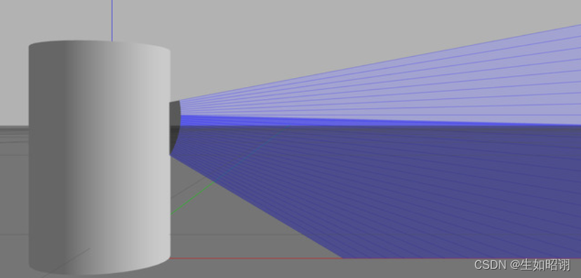
- 添加高斯噪声:
在< sensor >的子标签< ray >中添加如下代码:
<noise>
     <!-- Use gaussian noise -->
     <type>gaussian</type>
     <mean>0.0</mean>
     <stddev>0.1</stddev>
</noise>
效果如下:

- 通过Ctrl+T打开topic visualization查看:

总结
- 内容分析:本篇博客主要介绍了在Gazebo中如何使用SDF进行手动的编程建模,通过编写SDF文件,实现对于机器人从无到有的一步步建造,体会SDF文件的语法使用,并在文章整体使用两个具体实例,分别是轮式小车和Velodyne HDL-32 LiDAR传感器模型进行了深入研究。

- 注意:本文参考了Gazebo官方网站以及古月居中的Gazebo有关教程,主要目的是方便自行查询知识,巩固学习经验,无任何商业用途。
边栏推荐
- Stream通过findFirst()查找满足条件的一条数据
- 22家!北京昌平区通报存在食品安全问题餐饮服务企业
- 3DS MAX batch export file script MAXScript with interface
- Makefile missing separator. Stop.怎么解决「建议收藏」
- 接口自动化测试基础篇
- 借数据智能,亚马逊云科技助力企业打造品牌内生增长力
- I would like to ask the big guys, how to solve this error when cdc oracle initializes a 3 million table task running
- MySQL面试题整理
- SQL学习(基础)
- recursive recursive function
猜你喜欢
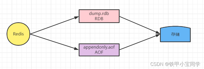
【学习笔记】Redis的持久化

机器学习实战(2)——端到端的机器学习项目
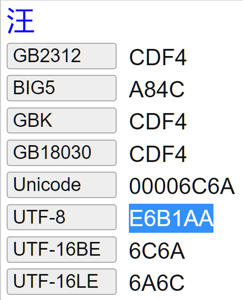
ABAP 里文件操作涉及到中文字符集的问题和解决方案试读版
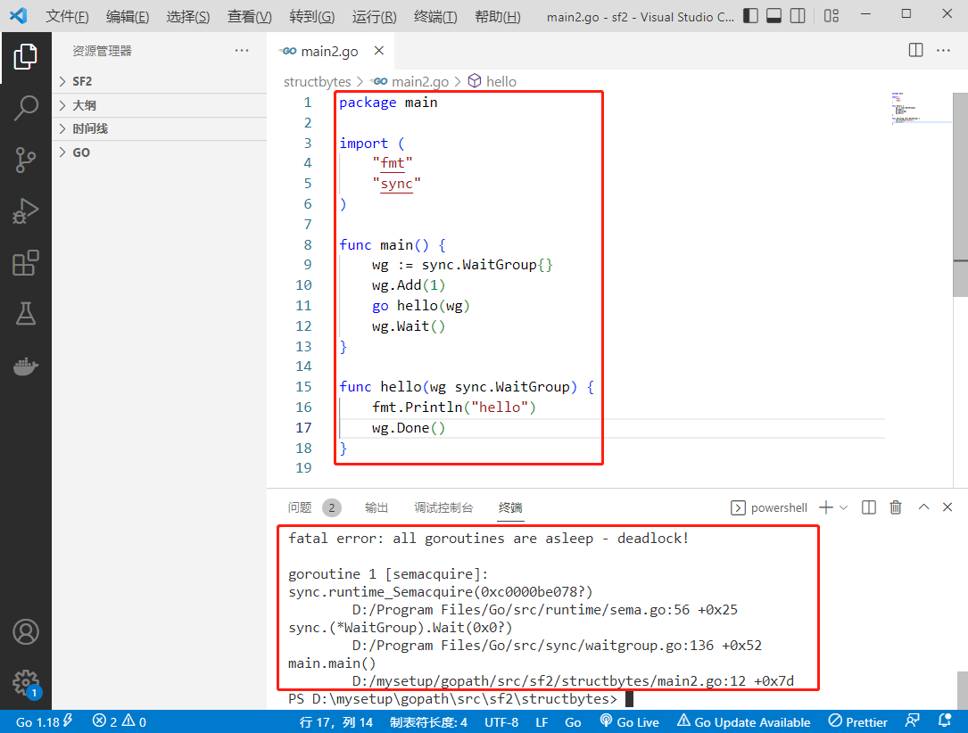
2022-08-09:以下go语言代码输出什么?A:否,会 panic;B:是,能正确运行;C:不清楚,看投票结果。 package main import ( “fmt“ “syn

友邦人寿可观测体系设计与落地
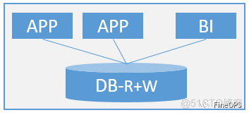
系统架构系列文章三--解决传统企业核心系统的性能问题
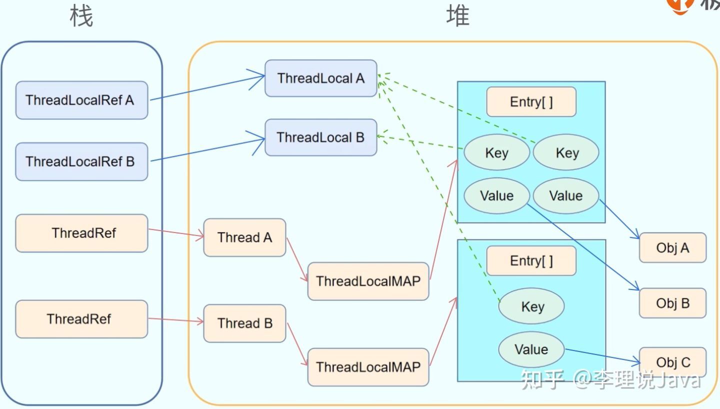
1W字详解线程本地存储 ThreadLocal

Error: Rule can only have one resource source (provided resource and test + include + exclude)
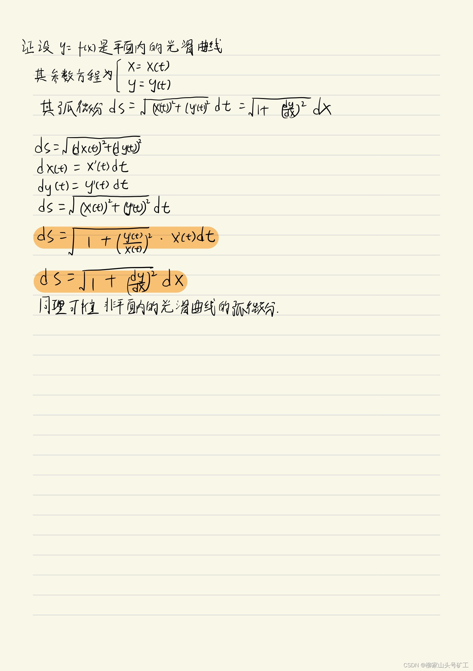
高数_证明_弧微分公式
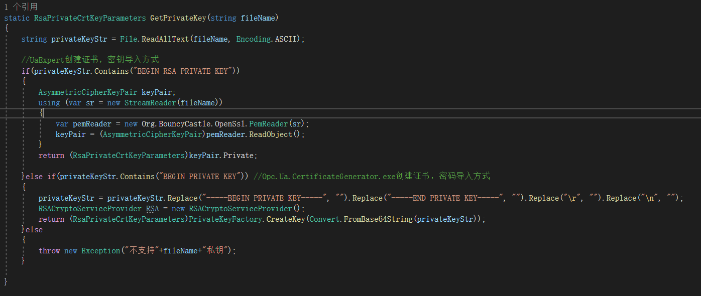
C#实现访问OPC UA服务器
随机推荐
22!Beijing Changping District notified catering service enterprises with food safety problems
the height of the landscape
发送post请求前台无法获取数据
记录几道整型提升的题目
机器学习实战(2)——端到端的机器学习项目
bgp双平面实验 路由策略控制流量
如何完成新媒体产品策划?
生成树协议STP(Spanning Tree Protocol)
Fragment的show和hide
CodeForces - 811A
The basic components of Loudi plant cell laboratory construction
MySQL面试题整理
文件系统设计
Basic knowledge of switches
How to describe multiple paragraphs with different font settings in Open Office XML format
一种能让大型数据聚类快2000倍的方法,真不戳
C#中导入其它自定义的命名空间
shell:常用小工具(sort、uniq、tr、cut)
ICML 2022 | 基于随机注意力机制的可解释可泛化图学习
A can make large data clustering method of 2000 times faster, don't poke