当前位置:网站首页>[Gazebo Introductory Tutorial] Lecture 3 Static/Dynamic Programming Modeling of SDF Files
[Gazebo Introductory Tutorial] Lecture 3 Static/Dynamic Programming Modeling of SDF Files
2022-08-10 13:53:00 【Born as Zhaoxu】
【Gazebo入门教程】第三讲 SDFfile static/Dynamic programming modeling

一、Customize the model and importGazebo
- 内容简介:This section takes a two-wheeled mobile robot as an example,Movement using a differential drive mechanism,从无到有,使用SDFFinished modeling and inGazeboto complete the simulation,The emphasis is on mastering how to use it through the careful process of modelingSDF文件和GazeboThe software completes the robot simulation.
1. Preparation for basic operations
- 注意:GazeboThe model file has strict requirements,Specific rules can be found hereSDF格式
\qquad ① 创建模型目录
mkdir -p ~/.gazebo/models/my_robot
\qquad ② 创建模型配置文件
gedit ~/.gazebo/models/my_robot/model.config
\qquad 元数据(config)内容如下:
	<?xml version="1.0"?>
	<model>
	  <name>My Robot</name>
	  <version>1.0</version>
	  <sdf version='1.4'>model.sdf</sdf>

	  <author>
	   <name>My Name</name>
	   <email>[email protected]</email>
	  </author>

	  <description>
	    My awesome robot.
	  </description>
	</model>
\qquad ② 创建模型配置文件
gedit ~/.gazebo/models/my_robot/model.sdf
\qquad Required marking(sdf)内容如下:
	<?xml version='1.0'?>
	<sdf version='1.4'>
	  <model name="my_robot">
	  </model>
	</sdf>
2. Build model base parts(静态)
- 基本要求:The content of this section is mainly to create the parts of the robot individually,For example the base、轮子等,Links such as related joint links are not involved,The point is to align the components,So the model is static,Ignore physical effects.
\qquad ① Make the robot model static
注意:在staticwill be after the labellinkGenerate corresponding parts under the label,通过collision的name隔开,Therefore, part of it will be ignored in the post-code display,请自行补充
	<?xml version='1.0'?>
	<sdf version='1.4'>
	  <model name="my_robot">
	  <static>true</static>
	  </model>
	</sdf>
\qquad ② Create the base of the box
代码解释:
- box 标签,Used to generate cuboids of the corresponding size
- collision 标签,Specifies the collision size
- visual 标签,Specifies visual dimensions,Commonly used with collision相同
<?xml version='1.0'?>
<sdf version='1.4'>
  <model name="my_robot">
  <static>true</static>
    <link name='chassis'>
      <pose>0 0 .1 0 0 0</pose>

      <collision name='collision'>
        <geometry>
          <box>
            <size>.4 .2 .1</size>
          </box>
        </geometry>
      </collision>

      <visual name='visual'>
        <geometry>
          <box>
            <size>.4 .2 .1</size>
          </box>
        </geometry>
      </visual>
    </link>
  </model>
</sdf>
\qquad ③ Create casters(万向轮)
注意:The casters are fixed to the base,So both belong to the samelink
<collision name='caster_collision'>
        <pose>-0.15 0 -0.05 0 0 0</pose>
        <geometry>
            <sphere>
            <radius>.05</radius>
          </sphere>
        </geometry>

        <surface>
          <friction>
            <ode>
              <mu>0</mu>
              <mu2>0</mu2>
              <slip1>1.0</slip1>
              <slip2>1.0</slip2>
            </ode>
          </friction>
        </surface>
      </collision>

      <visual name='caster_visual'>
        <pose>-0.15 0 -0.05 0 0 0</pose>
        <geometry>
          <sphere>
            <radius>.05</radius>
          </sphere>
        </geometry>
      </visual>
    </link>
\qquad ④ Create the front and rear wheels
注意:New front and rear wheels were created separatelylink
	  <link name="left_wheel">
      <pose>0.1 0.13 0.1 0 1.5707 1.5707</pose>

      <collision name="collision">
        <geometry>
          <cylinder>
            <radius>.1</radius>
            <length>.05</length>
          </cylinder>
        </geometry>
      </collision>

      <visual name="visual">
        <geometry>
          <cylinder>
            <radius>.1</radius>
            <length>.05</length>
          </cylinder>
        </geometry>
      </visual>
    </link>

    <link name="right_wheel">
      <pose>0.1 -0.13 0.1 0 1.5707 1.5707</pose>

      <collision name="collision">
        <geometry>
          <cylinder>
            <radius>.1</radius>
            <length>.05</length>
          </cylinder>
        </geometry>
      </collision>

      <visual name="visual">
        <geometry>
          <cylinder>
            <radius>.1</radius>
            <length>.05</length>
          </cylinder>
        </geometry>
      </visual>
    </link>
\qquad ⑤ 导入Gazebo可视化模型
- 使用INSERTImport the model in the corresponding folder,The model can be seen as follows:

注意:修改SDF文件后,Just delete the original model and re-insert it to update the model
3. Create jointed parts(动态)
- 基本要求:将static设为false,Add hinge joints for the left and right wheels,joint aroundY轴旋转,Attach each wheel to the chassis
<static>false</static>
	<joint type="revolute" name="left_wheel_hinge">
      <pose>0 0 -0.03 0 0 0</pose>
      <child>left_wheel</child>
      <parent>chassis</parent>
      <axis>
        <xyz>0 1 0</xyz>
      </axis>
    </joint>

    <joint type="revolute" name="right_wheel_hinge">
      <pose>0 0 0.03 0 0 0</pose>
      <child>right_wheel</child>
      <parent>chassis</parent>
      <axis>
        <xyz>0 1 0</xyz>
      </axis>
    </joint>
4. GazeboBasic emulation
- 基本操作:启动Gazebo,Insert the latest model,Open the hidden right panel,Select the model you want to control,As shown belowForceThe joint forces below are modified,The robot will move:

二、创建Velodyne HDL-32 LiDAR传感器
- 内容简介:This section takes a two-wheeled mobile robot as an example,Movement using a differential drive mechanism,从无到有,使用SDFFinished modeling and inGazeboto complete the simulation,The emphasis is on mastering how to use it through the careful process of modelingSDF文件和GazeboThe software completes the robot simulation.
1. Create the base world
- 创建新的
.world文件:
gedit velodyne.world
- The environment in which the world is created:ground and light
<?xml version="1.0" ?>
<sdf version="1.5">
  <world name="default">

    <!-- A global light source -->
    <include>
      <uri>model://sun</uri>
    </include>

    <!-- A ground plane -->
    <include>
      <uri>model://ground_plane</uri>
    </include>
  </world>
</sdf>
2. Create a static model of the sensor
- Sensor base part2D绘图如下:

- 对应代码如下:位于< world >的内部
<model name="velodyne_hdl-32">
  <!-- Give the base link a unique name -->
  <link name="base">

    <!-- Offset the base by half the lenght of the cylinder -->
    <pose>0 0 0.029335 0 0 0</pose>
    <collision name="base_collision">
      <geometry>
        <cylinder>
          <!-- Radius and length provided by Velodyne -->
          <radius>.04267</radius>
          <length>.05867</length>
        </cylinder>
      </geometry>
    </collision>

    <!-- The visual is mostly a copy of the collision -->
    <visual name="base_visual">
      <geometry>
        <cylinder>
          <radius>.04267</radius>
          <length>.05867</length>
        </cylinder>
      </geometry>
    </visual>
  </link>

  <!-- Give the base link a unique name -->
  <link name="top">

    <!-- Vertically offset the top cylinder by the length of the bottom cylinder and half the length of this cylinder. -->
    <pose>0 0 0.095455 0 0 0</pose>
    <collision name="top_collision">
      <geometry>
        <cylinder>
          <!-- Radius and length provided by Velodyne -->
          <radius>0.04267</radius>
          <length>0.07357</length>
        </cylinder>
      </geometry>
    </collision>

    <!-- The visual is mostly a copy of the collision -->
    <visual name="top_visual">
      <geometry>
        <cylinder>
          <radius>0.04267</radius>
          <length>0.07357</length>
        </cylinder>
      </geometry>
    </visual>
  </link>
</model>
- 启动Gazebo查看模型:(先cd到文件路径下)
	cd ~/
	gazebo velodyne.world -u

- View collision properties:Right click on the model,view→Collisions

3. Add model inertia
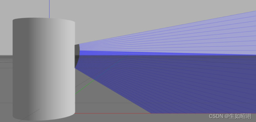
- 3.1 View the current inertia value:Right click on the model,选择View->Inertia

注意:The purple box corresponds to the associated link size,At this point the model has no inertial information,Therefore the size is too large
- 3.2 Add inertia information:质量设为1.3kg,Add the corresponding mass and inertia matrices
在< link name=“base” >块中添加以下内容:
  <link name="base">
    <pose>0 0 0.029335 0 0 0</pose>
    <inertial>
      <mass>1.2</mass>
      <inertia>
        <ixx>0.001087473</ixx>
        <iyy>0.001087473</iyy>
        <izz>0.001092437</izz>
        <ixy>0</ixy>
        <ixz>0</ixz>
        <iyz>0</iyz>
      </inertia>
    </inertial>
在< link name=“top” >块中添加以下内容:
 <link name="top">
   <pose>0 0 0.095455 0 0 0</pose>
   <inertial>
     <mass>0.1</mass>
     <inertia>
       <ixx>0.000090623</ixx>
       <iyy>0.000090623</iyy>
       <izz>0.000091036</izz>
       <ixy>0</ixy>
       <ixz>0</ixz>
       <iyz>0</iyz>
     </inertia>
   </inertial>
最终效果如下:

4. 添加关节
- 4.1 Defines the top rotation joint around the bottom,在< world >最后添加内容如下:
<!-- Each joint must have a unique name -->
<joint type="revolute" name="joint">

  <!-- Position the joint at the bottom of the top link -->
  <pose>0 0 -0.036785 0 0 0</pose>

  <!-- Use the base link as the parent of the joint -->
  <parent>base</parent>

  <!-- Use the top link as the child of the joint -->
  <child>top</child>

  <!-- The axis defines the joint's degree of freedom -->
  <axis>

    <!-- Revolve around the z-axis -->
    <xyz>0 0 1</xyz>

    <!-- Limit refers to the range of motion of the joint -->
    <limit>

      <!-- Use a very large number to indicate a continuous revolution -->
      <lower>-10000000000000000</lower>
      <upper>10000000000000000</upper>
    </limit>
  </axis>
</joint>
- 4.2 检验效果:
1. 启动Gazebo,Right click on the model,选择View->Joints,View->Transparent

2. Open the right panel,选择Velodyne模型.使用ForceTabs apply smaller ones to the joints,You can see the joints rotate

5. 添加传感器
- Basic sensor information:
激光传感器,One or more beams can be emitted,The beam produces distance and intensity data,对应SDF文件中的< scan >和< range >,Corresponding to the beam layout respectively、Quantity and properties of bound bundles,其中< scan >中包含< horizontal >和< vertical >两个块.< horizontal >Components define the rays emitted in the horizontal plane,该< vertical >Components define rays emitted in a vertical plane,VelodyneThe sensor needs vertical rays,然后旋转.We model it as a rotating horizontal sector.
- Add and set up sensors:(Add the following in the last section of )
<!-- Add a ray sensor, and give it a name -->
<sensor type="ray" name="sensor">

  <!-- Position the ray sensor based on the specification. Also rotate it by 90 degrees around the X-axis so that the <horizontal> rays become vertical -->
  <pose>0 0 -0.004645 1.5707 0 0</pose>

  <!-- Enable visualization to see the rays in the GUI -->
  <visualize>true</visualize>

  <!-- Set the update rate of the sensor -->
  <update_rate>30</update_rate>
  <ray>

  <!-- The scan element contains the horizontal and vertical beams. We are leaving out the vertical beams for this tutorial. -->
  <scan>

    <!-- The horizontal beams -->
    <horizontal>
      <!-- The velodyne has 32 beams(samples) -->
      <samples>32</samples>

      <!-- Resolution is multiplied by samples to determine number of simulated beams vs interpolated beams. See: http://sdformat.org/spec?ver=1.6&elem=sensor#horizontal_resolution -->
      <resolution>1</resolution>

      <!-- Minimum angle in radians -->
      <min_angle>-0.53529248</min_angle>

      <!-- Maximum angle in radians -->
      <max_angle>0.18622663</max_angle>
    </horizontal>
  </scan>

  <!-- Range defines characteristics of an individual beam -->
  <range>

    <!-- Minimum distance of the beam -->
    <min>0.05</min>

    <!-- Maximum distance of the beam -->
    <max>70</max>

    <!-- Linear resolution of the beam -->
    <resolution>0.02</resolution>
  </range>
</ray>
</sensor>
- Check out the simulation effect:
- 添加高斯噪声:
在< sensor >的子标签< ray >中添加如下代码:
<noise>
     <!-- Use gaussian noise -->
     <type>gaussian</type>
     <mean>0.0</mean>
     <stddev>0.1</stddev>
</noise>
效果如下:

- 通过Ctrl+T打开topic visualization查看:

总结
- 内容分析:本篇博客主要介绍了在Gazebo中如何使用SDFDo manual programming modeling,通过编写SDF文件,Realize the step-by-step construction of robots from scratch,体会SDFThe syntax of the file is used,And use two specific examples throughout the article,Wheeled trolleys and Velodyne HDL-32 LiDARThe sensor model is studied in depth.

- 注意:本文参考了Gazebo官方网站以及古月居中的Gazebo有关教程,主要目的是方便自行查询知识,巩固学习经验,无任何商业用途.
边栏推荐
- Efficient and Robust 2D-to-BEV Representation Learning via Geometry-guided Kernel Transformer Paper Notes
- Network Saboteur
- AWS Security Fundamentals
- recursive recursive function
- 一个 CRM One Order Application log 的单元测试报表
- 交换机的基础知识
- How to describe multiple paragraphs with different font settings in Open Office XML format
- Ethernet channel Ethernet channel
- 【ECCV 2022|Millions of Prizes】PSG Competition: Pursuing the "Most Comprehensive" Scene Understanding
- tampercfg内核模块导致机器频繁crash
猜你喜欢
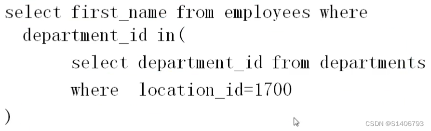
SQL学习(基础)

友邦人寿可观测体系设计与落地

Nanodlp v2.2/v3.0 light curing circuit board, connection method of mechanical switch/photoelectric switch/proximity switch and system state level setting
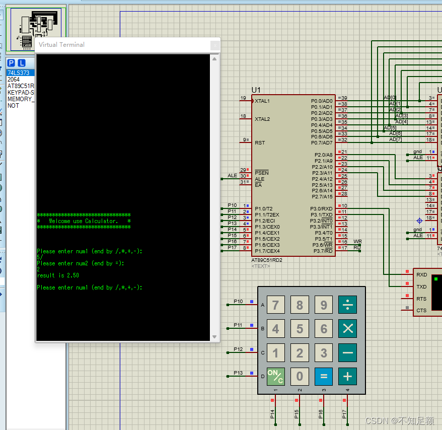
Matrix Keyboard & Calculator Small Project Based on 51 (UcosII)

M²BEV: Multi-Camera Joint 3D Detection and Segmentation with Unified Bird’s-Eye View Representation
【JS高级】ES5标准规范之创建子对象以及替换this_10
MySQL - 数据库的存储引擎
雨水中存在的PFAS化学物质对饮用水安全构成了威胁
矩阵键盘&基于51(UcosII)计算器小项目
M²BEV: Multi-Camera Joint 3D Detection and Segmentation with Unified Bird’s-Eye View Representation
随机推荐
How to describe multiple paragraphs with different font settings in Open Office XML format
Efficient and Robust 2D-to-BEV Representation Learning via Geometry-guided Kernel Transformer 论文笔记
Fragment-hide和show
2022-08-09:以下go语言代码输出什么?A:否,会 panic;B:是,能正确运行;C:不清楚,看投票结果。 package main import ( “fmt“ “syn
雨水中存在的PFAS化学物质对饮用水安全构成了威胁
Network Saboteur
学习日记9
Stream通过findFirst()查找满足条件的一条数据
Redis 定长队列的探索和实践
递归递推之递归的函数
开源SPL消灭数以万计的数据库中间表
C#报错 The ‘xmins‘ attribute is not supported in this context
图式图例规范尺寸
YTU 2295: KMP pattern match one (string)
Lithium battery technology
黑客入门,从HTB开始
NAACL 2022 | 简单且高效!随机中间层映射指导的知识蒸馏方法
用低代码驱动IT现代化
汉字检测和关键词检测
第三方软件测评有什么作用?权威软件检测机构推荐