当前位置:网站首页>Deep understanding of modern mobile GPU (continuously updating)
Deep understanding of modern mobile GPU (continuously updating)
2022-04-23 21:00:00 【Descosmos】
List of articles
GPU brief introduction
GPU And CPU The difference between
CPU Its full name is (Central Processing Unit) a central processor , and GPU Its full name is (Graphics Processor Unit) Graphics processing element . generally speaking ,GPU Used for task scenarios that require multithreading , and CPU It is used for large , Highly branched task scenarios .
Parallelism
The architecture in which each graphic program executes the same instruction on different threads is called Single Instruction, Multiple Data (SIMD), The advantage of this architecture is that : For properly structured programs , A large number of threads can process it at the same time , great
Improved operational efficiency .
Vector processing and scalar processing
Vector processing
Vector processing is a method that can process multiple data at one time , This method is very efficient in dealing with color and vertex . But if you deal with scalar data , Or the processed data is less than the minimum value expected by the processor , Then the bandwidth of the vector processor will be wasted . for example : Usual vector bandwidth
by 4, This means that if the shader (Shader) Only one scalar can be processed at a time , Then the efficiency is 25%.
Scalar processing
Scalar processors tend to be more flexible in the operations that can be performed per hardware cycle , Because it doesn't need data to fill additional bandwidth .
Vertex shader and Fragment shader
generally speaking , The rendering process is as follows :

Vertex shader
Vertex Is vertex data , It determines the size of the part to be rendered and the boundary information ;
Fragment shader
Fragment Is the information unit corresponding to each pixel . One pixel (pixel) Corresponding to one fragment, but fragment It also contains pixel colors , Pixel depth value and other information .
TBR, TBDR And IMR
IMR
at present PC Terminal GPU Most of them adopt this architecture , The main feature of this architecture is the fast processing speed , But at the same time, the power consumption is also large , Therefore, the mobile terminal has strict requirements for power consumption , Therefore, this architecture is generally not applicable to the mobile terminal GPU.
TBR
stay GPU During rendering , The biggest factor affecting power consumption is bandwidth (bandwidth), and GPU The biggest scenario for using bandwidth is with the... Located in the system memory FrameBuffer Interact .IMR Each pixel is processed with FrameBuffer Interact , As a result GPU Use bandwidth frequently , It brings huge power consumption .
The solution of the mobile terminal is : It's going to be huge FrameBuffer Break down into many small pieces , So that each small piece can be separated gpu The closer one SRAM It can hold , The number of blocks depends on your hardware SRAM Size . such GPU The original access can be FrameBuffer The operation is transferred to each small piece SRAM.
When all the data is processed , Then turn the whole back to DRAM On . This reduces GPU For the use of bandwidth , Reduced power consumption .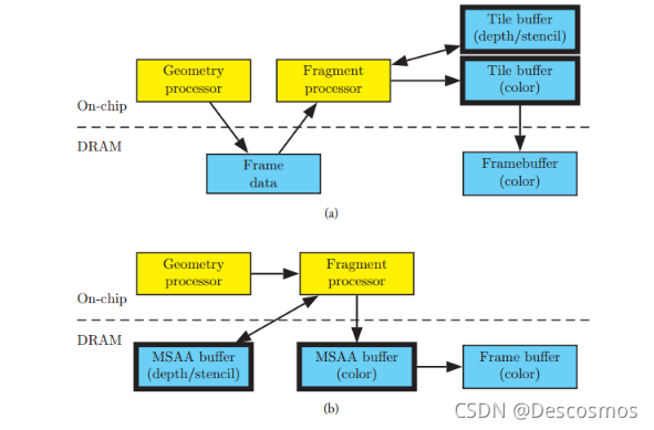
a yes TBR, Here is IMR, Here you can see TBR On the pipeline of PixelShader One more step has been added before , namely vs and gs Processed data ( It's called FrameData) It was temporarily preserved and lined up , Then later on framebuffer Block , Then for each piece , Draw all that affect this block pixel.
FrameData This is tbr Unique in gpu Storage data required for drawing , stay powervr It's called arguments buffer, stay arm It's called plolygon lists.FrameData Will always save up and know something that must be drawn to framebuffer Last time , It means tbdr
tbdr Under the architecture of commandbuffer Will not be executed immediately , Just accumulate to a certain point in time . and glclear This operation can put the current framedata Empty , This will save a lot of unnecessary drawing .
Early-Z
When opaque elements from Rasterize When the phase starts processing pixel by pixel , First of all to Depth Read & Test, Directly after passing Write, Then execute the... On the pixel PS Program , Otherwise, you can stop and rest and wait for the next pixel to be processed . Simply speaking , That is to do depth detection before drawing , Reduce unnecessary drawing .
This is why when rendering opaque objects, we should take the drawing from near to far , Because the nearby objects may block the distant objects after drawing .
however , be based on EarlyZ It cannot be completely avoided Overdraw Of . Because it is impossible to draw a really complex scene strictly from near to far .
TBDR(Tile-Based Deferred Rendering)
TBDR It's right TBR Further improvements in technology , Its improvement lies in the addition of HSR(Hidden Surface Removal) technology .
TBDR The principle of technology is : Capture the entire scene before you start rendering , Therefore, the occluded pixels are recognized before processing , Avoid waste of resources . meanwhile , The hardware began to divide the geometry into smaller rectangular areas , Each rectangular area will be represented as a graph
Handle , Such areas are called "Tiles", every last tile Regions are rasterized and processed independently . secondly , Because of each tile Small enough , Therefore, we can directly use GPU Of memory , Greatly improved GPU Work efficiency .
Delayed rendering means : Will all texturing Texturing and Shading To color Postpone the operation to Visible when all pending objects are verified after ." verification " Operation by HSR And depth detection are completed .
HSR(Hidden Surface Removal)
OverDraw When the pixels of a drawn object are covered by the pixels of another object , The covered part is called OverDraw.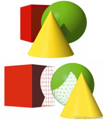
- stay IMR Structural GPU in , This scene will first draw the complete cube and sphere , Then draw the cone , The drawing of cone and sphere will block some other painted pixels , This part of the occluded pixels produces OverDraw.
- stay TBDR Structural GPU in , This scene will first calculate all the pixels that will be occluded , Wait until all occluded pixels are " exclude " After cleaning , For further drawing . But pay attention to ,HSR In a complex scene, it won't completely " exclude " Occluded pixels , That means
OverDraw The value of may not be 0.
principle : When the pixel passes Early-Z Prepare to carry out PS Before drawing , First, only record the pixel to which primitive to draw . When it's time Tile All the elements on the are processed , Then start to draw the marked pixel points that can be drawn in each primitive .
summary
- TBR And TBDR All are take Rasterize/PS The processing of was delayed until all VS after , and IMR It is VS In a minute Rasterize/PS.
- TBR And TBDR The difference is :TBDR One more step in the rendering architecture Rasterize To PS Delay of , This step is called HSR.
TBR: VS->Defer->RS->PS
TBDR: VS->Defer->RS->Defer->PS
PowerVR GPU
PowerVR GPU yes Imagination Technologies It's a product of research and development GPU framework , All its generations are based on Tile Based Deferred Rendering(TBDR) structure , The core design principle of the structure is : Try to keep the bandwidth of graphics hardware
Minimum demand .
Vertex Processing(Tiler)
GPU Processing geometric data generally includes the following steps :
- Perform application defined transformations , For example, vertex shader (Vertex Processing).
- Convert the generated data into screen space (Clip, Poject, Cill).
- Tile Accelerator(TA) Decide which one. tile Which converted element is included in the (primitive) (Tiling).
- Update each tile lists( Block list ), To track elements that fall within the boundaries of each block .

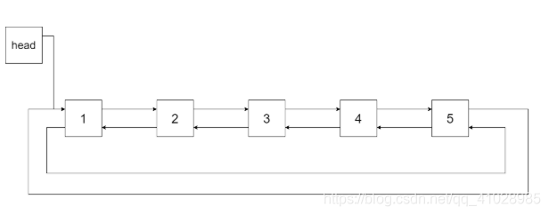
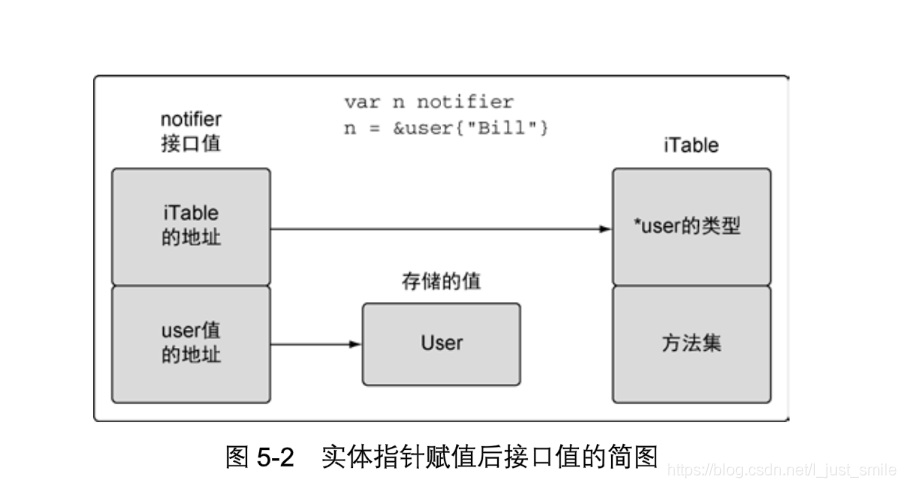
After handling the above steps ,tile lists Each of the tile All contain a list of elements , These entity lists contain pointers to the converted vertex data . tile list and Converted vertex The data is stored in a file called Parameter Buffer(PB) Parameter buffer ,
The buffer is located in the system memory , from GPU Dispatch , It stores all the information needed to render the block .
Per-Tile Rasterization (Renderer)
The rasterization and pixel coloring process is based on each tile, The specific process is as follows :
- Corresponding tile list From the parameter buffer (PB) It is proposed that , To determine the screen space primitive data to be obtained .
- Image Synthesis Processor (ISP) After the graphics synthesis processor obtains the primitive data, it executes HSR, At the same time depth and stencil test .ISP Only get the screen spatial position data of the geometry in the block .
- Tag Buffer It contains the information of the top triangle corresponding to each pixel .
- Texture and shading processor Texture and Shading Processor (TSP), Then proceed with the dyeing operation .
- And then Alpha testing and Alpha blending operation .
- once tile Render completed , The color data will be written into the system memory frame buffer in .

Unified and non-unified shader architectures
Shader There are two structures of shaders : Unity and disunity .
- Unified structure shader Processing fragment and vertex shaders The same processing module will be used ;
- Not of uniform structure shader Processing fragment and vertex shaders Different processing modules will be used .


Firmware
In most of GPU Architecture , Graphics hardware events are to be handed over to CPU Internal image driver for processing . and PowerVR This part consists of firmware complete , This ensures that GPU Able to handle most graphics events internally , In order to reduce CPU The burden of , Increased efficiency .
Tile Accelerator(TA)
PowerVR Hardware unit , Used to determine each Tile Which elements are included .
This information is called per-tile list, This list as well as geometry The data is stored in a file called **Parameter Buffer(PB)** The cache , This cache is in System Memory in .
Image Signal Processor(ISP)
PowerVR Graphics processing unit , To deal with a Tile Of EarlyDT、 Rasterization and depth template testing .
Texture and Shading Processor (TSP)
The hardware unit responsible for processing the fragment shader , This process is also one by one Tile Of , When one Tile When rendering is complete , The color data will be written System Memory.
ISP(Image Synthesis Processor)
ISP Is used to handle every tile Of HSR step , Make sure that only after TSP(Texture and Shading Processor) After that fragments Will eventually affect the rendered image .
After opening the depth test ,ISP from SystenmMemory Of PB Read from Primitive List, That is, primitive data . And then Drive alignment based on elements Tile Each visible element in the projection ray , To accurately calculate
The depth of each pixel in the primitive , Compare it with the depth of the corresponding pixel in the depth buffer to decide whether to discard this pixel .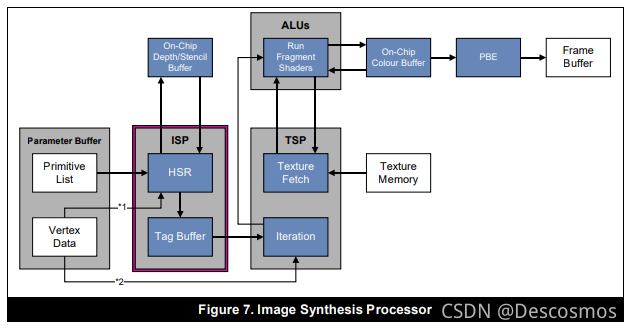
therefore ,HSR The function is in Tile Do it once for each pixel of each primitive in the Early-DT. General Early-DT If you don't know the pixel depth , Only according to front to back Process in the order of . and HSR Is characterized by Tile In all of the
Calculate the minimum depth of pixels with rays , Save a lot of work .
QCom GPU
Reference material
For mobile TBDR framework GPU Rendering optimization of features
Mobile devices GPU Architecture knowledge summary
A look at the PowerVR graphics architecture: Tile-based rendering
Graphics rendering notes
Adreno Vulkan Developer Guide
版权声明
本文为[Descosmos]所创,转载请带上原文链接,感谢
https://yzsam.com/2022/111/202204210545297854.html
边栏推荐
- South Korea may ban apple and Google from offering commission to developers, the first in the world
- Valueerror: invalid literal for int() with base 10 conversion error related to data type
- 常用60类图表使用场景、制作工具推荐
- Centos7 builds MySQL master-slave replication from scratch (avoid stepping on the pit)
- 小米手机全球已舍弃“MI”品牌,全面改用“xiaomi”全称品牌
- Is qiniu school useful and is the recommended securities account safe
- 浅谈数据库设计之三大范式
- 亚马逊和Epic将入驻,微软应用商城向第三方开放
- How to play the guiding role of testing strategy
- The iswow64process function determines the number of program bits
猜你喜欢

Use 3080ti to run tensorflow GPU = 1 X version of the source code

Rust更适合经验较少的程序员?
Write table of MySQL Foundation (create table)
Question brushing plan - depth first search (II)
go interface

Keywords static, extern + global and local variables
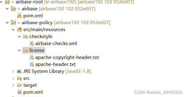
airbase 初步分析
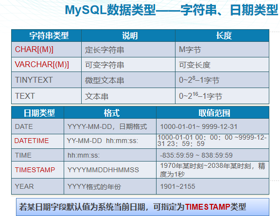
MySQL basic collection
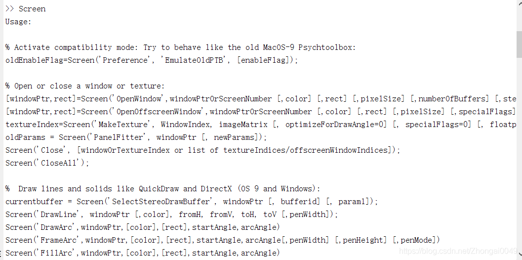
Matlab: psychtoolbox installation
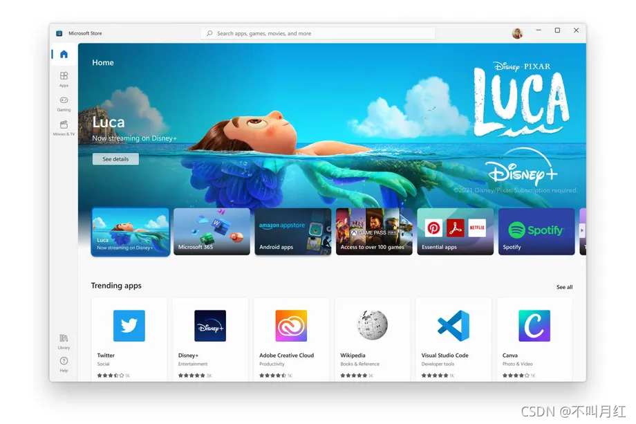
亚马逊和Epic将入驻,微软应用商城向第三方开放
随机推荐
LeetCode-279-完全平方数
laravel 发送邮件
Flomo software recommendation
go struct
Use 3080ti to run tensorflow GPU = 1 X version of the source code
管道和xargs
常用60类图表使用场景、制作工具推荐
Xiaomi mobile phone has abandoned the "Mi" brand all over the world and switched to the full name brand of "Xiaomi"
Centralized record of experimental problems
MySQL基础合集
Reentrant function
Summary and effect analysis of methods for calculating binocular parallax
学会打字后的思考
笔记本电脑卡顿怎么办?教你一键重装系统让电脑“复活”
Linux中,MySQL的常用命令
Go limit depth traversal of files in directory
Ubutnu20 installer centernet
Fastdfs思维导图
Introduce structured concurrency and release swift 5.5!