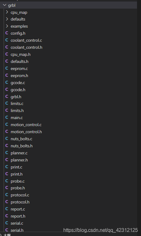
当前位置:网站首页>Grbl learning (I)
Grbl learning (I)
2022-04-23 15:55:00 【Sola_ Ex】
GRBL Study
GRBL Introduction to
Grbl Is used for CNC The motion control of milling based on parallel port is absolutely , High performance , Low cost alternatives . Just run Atmega 328, It will be Arduino(Duemillanove / Uno) Up operation .
The controller is highly optimized C Language writing , utilize AVR All the ingenious functions of the chip to realize accurate timing and asynchronous operation . It can last up to 30kHz The stability of the , Jitter free control pulse .
It accepts... That meets the standards g Code , And has passed a variety of CAM The output of the tool is tested , No problem . Fully support arc , Circular and helical motion , And all other major g Code command . Macro functions are not supported , Variables and most fixed loops , But we think that GUI They can be better converted into direct g Code .
GRBL Of GitHub Warehouse
Start with the file directory
Just from GitHub Downloaded grbl after , It can be used directly vscode Open the whole folder , remove git Some documents and readme outside , In fact, only 3 A folder :
- build
- doc
- grbl
In fact, it seems to know ,build and doc It has nothing to do with the source code , They will only include some files stored after compilation or some description documents, or some dependent scripts that need to be downloaded during compilation . about Arduino Come on , Not all source files or dependent files will appear in the project , More time , After selecting some chips , By writing in advance py Script , Automatically link and download the corresponding chip dependency file , So as to reduce the capacity of the whole project .
Get into GRBL
cpu_map
The focus of the whole warehouse is grbl This folder .
As you can see from the diagram ,grbl In the folder of , contain :
- cpu_map
- defaults
- examples
- Related driver files
from cpu_map You can see , It contains two header files , namely :
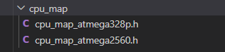
That's what I've just introduced GRBL Described when , Support 328P and 2560 Two AVR chip . These two are also Arduino The classic of development board ( It is estimated that foreigners like Arduino, After all, it's easy to use ).
If you want to transplant, of course, you must know what's inside , After opening it, it's like this :
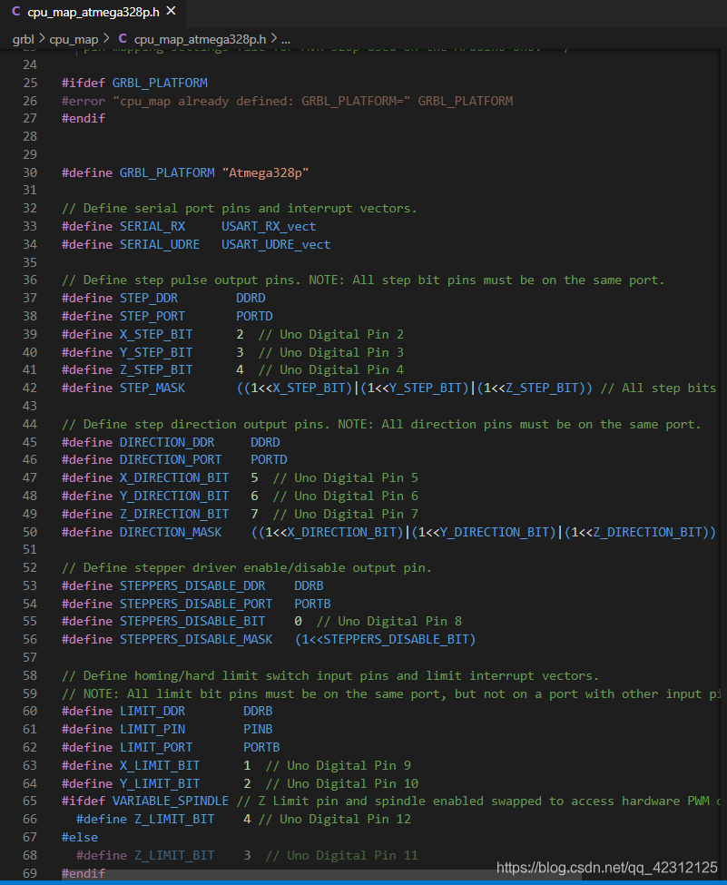
Analyze it bit by bit :
#define GRBL_PLATFORM "Atmega328p"
Here is used to define the name of the chip , It's easy to understand .
// Define serial port pins and interrupt vectors.
#define SERIAL_RX USART_RX_vect
#define SERIAL_UDRE USART_UDRE_vect
This place , It is used to define the pin and interrupt vector of the serial port .
// Define step pulse output pins. NOTE: All step bit pins must be on the same port.
#define STEP_DDR DDRD
#define STEP_PORT PORTD
#define X_STEP_BIT 2 // Uno Digital Pin 2
#define Y_STEP_BIT 3 // Uno Digital Pin 3
#define Z_STEP_BIT 4 // Uno Digital Pin 4
#define STEP_MASK ((1<<X_STEP_BIT)|(1<<Y_STEP_BIT)|(1<<Z_STEP_BIT)) // All step bits

// Define step direction output pins. NOTE: All direction pins must be on the same port.
#define DIRECTION_DDR DDRD
#define DIRECTION_PORT PORTD
#define X_DIRECTION_BIT 5 // Uno Digital Pin 5
#define Y_DIRECTION_BIT 6 // Uno Digital Pin 6
#define Z_DIRECTION_BIT 7 // Uno Digital Pin 7
#define DIRECTION_MASK ((1<<X_DIRECTION_BIT)|(1<<Y_DIRECTION_BIT)|(1<<Z_DIRECTION_BIT)) // All direction bits

// Define stepper driver enable/disable output pin.
#define STEPPERS_DISABLE_DDR DDRB
#define STEPPERS_DISABLE_PORT PORTB
#define STEPPERS_DISABLE_BIT 0 // Uno Digital Pin 8
#define STEPPERS_DISABLE_MASK (1<<STEPPERS_DISABLE_BIT)

// Define homing/hard limit switch input pins and limit interrupt vectors.
// NOTE: All limit bit pins must be on the same port, but not on a port with other input pins (CONTROL).
#define LIMIT_DDR DDRB
#define LIMIT_PIN PINB
#define LIMIT_PORT PORTB
#define X_LIMIT_BIT 1 // Uno Digital Pin 9
#define Y_LIMIT_BIT 2 // Uno Digital Pin 10
#ifdef VARIABLE_SPINDLE // Z Limit pin and spindle enabled swapped to access hardware PWM on Pin 11.
  #define Z_LIMIT_BIT 4 // Uno Digital Pin 12
#else
  #define Z_LIMIT_BIT 3 // Uno Digital Pin 11
#endif
#define LIMIT_MASK ((1<<X_LIMIT_BIT)|(1<<Y_LIMIT_BIT)|(1<<Z_LIMIT_BIT)) // All limit bits
#define LIMIT_INT PCIE0 // Pin change interrupt enable pin
#define LIMIT_INT_vect PCINT0_vect
#define LIMIT_PCMSK PCMSK0 // Pin change interrupt register
Is this paragraph very long ? But take a closer look , Nothing ,GRBL In fact, printing is realized by controlling the motor , Similar to 3D Printer i3 Structure . So we need to define :
- X/Y/Z Direction control pin , This pin is used to control the operation direction of the motor .
- Stepper motor enable pin , That is to control whether the stepping motor can move through this pin .
- Limit switch detection pin , That is, the motor is moving to 0 A.m. , After triggering the limit switch , Need to stop right now , Otherwise, it is easy to damage the machine structure .
Analyze it like this , It's easy .
// Define probe switch input pin.
#define PROBE_DDR DDRC
#define PROBE_PIN PINC
#define PROBE_PORT PORTC
#define PROBE_BIT 5 // Uno Analog Pin 5
#define PROBE_MASK (1<<PROBE_BIT)

// Start of PWM & Stepper Enabled Spindle
#ifdef VARIABLE_SPINDLE
  // Advanced Configuration Below You should not need to touch these variables
  #define PWM_MAX_VALUE 255.0
  #define TCCRA_REGISTER TCCR2A
  #define TCCRB_REGISTER TCCR2B
  #define OCR_REGISTER OCR2A

  #define COMB_BIT COM2A1
  #define WAVE0_REGISTER WGM20
  #define WAVE1_REGISTER WGM21
  #define WAVE2_REGISTER WGM22
  #define WAVE3_REGISTER WGM23

  // NOTE: On the 328p, these must be the same as the SPINDLE_ENABLE settings.
  #define SPINDLE_PWM_DDR DDRB
  #define SPINDLE_PWM_PORT PORTB
  #define SPINDLE_PWM_BIT 3 // Uno Digital Pin 11
about GRBL for , Use CNC Words , With the function of laser head , The laser head uses PWM Control mode control , Of course, it also has a probe .
There are so many general analysis , In fact, you can go and see 2560 The header file , You'll find it's basically the same . Therefore, these two header files directly indicate , Use it normally GRBL Words ,MCU What function pins need to be provided . So we can also start the first step of transplantation ------ Pin assignments .
defaults
After entering , See several defaults Header file starting with name , Careful can be found on the name , This should be an adaptive configuration according to different models .
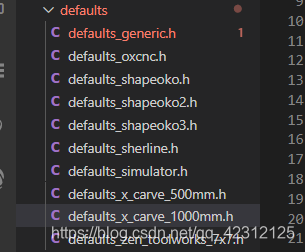
You can open any file to see :
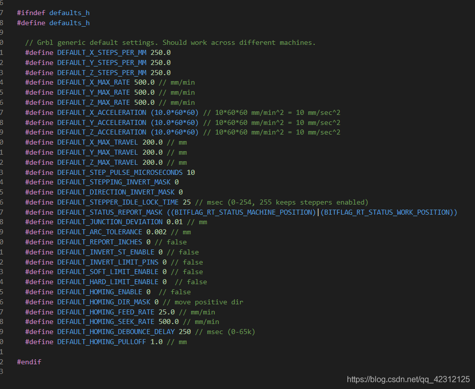
you 're right , The file is extremely simple , It's just a configuration file ! Used to configure CNC Related parameters of , For example, the number of pulses of the motor and so on . Specific configuration , When transplanting later, if you encounter , Let's go into more detail .
examples
This folder is useless , It's in there Arduino Engineering documents of . because GRBL Is based on Arduino It's done , So the compiler will use Arduino To compile .
The rest of the transplants are analyzed one by one .
Transplant preparation
For this GRBL Transplantation , I intend to transplant it to two chips :
- STM32F446RC
- i.MX RT1010 EVK ( I applied to ! Happy !)
One is M4 One of the kernel is M7 The kernel of , because GRBL The motion has a computational complement algorithm , Choosing a chip with floating-point operation will feel very good .
… Development board design …ing!
版权声明
本文为[Sola_ Ex]所创,转载请带上原文链接,感谢
https://yzsam.com/2022/04/202204231554163751.html
边栏推荐
- Neodynamic Barcode Professional for WPF V11. 0
- 多生成树MSTP的配置
- 捡起MATLAB的第(3)天
- Compile, connect -- Notes
- [open source tool sharing] MCU debugging assistant (oscillograph / modification / log) - linkscope
- [split of recursive number] n points K, split of limited range
- js正則判斷域名或者IP的端口路徑是否正確
- Temporal model: long-term and short-term memory network (LSTM)
- Why is IP direct connection prohibited in large-scale Internet
- js正则判断域名或者IP的端口路径是否正确
猜你喜欢
C language --- advanced pointer

糖尿病眼底病变综述概要记录
MySQL - MySQL查询语句的执行过程
C#,贝尔数(Bell Number)的计算方法与源程序
Spark 算子之distinct使用
Redis master-slave replication process
C语言自编字符串处理函数——字符串分割、字符串填充等
MySQL optimistic lock to solve concurrency conflict
Method 2 of drawing ROC curve in R language: proc package
Configuration of multi spanning tree MSTP
随机推荐
C语言自编字符串处理函数——字符串分割、字符串填充等
ESP32编译环境的搭建
【第5节 if和for】
Application of Bloom filter in 100 million flow e-commerce system
Distinct use of spark operator
Ice -- source code analysis
One brush 313 sword finger offer 06 Print linked list from end to end (E)
Date date calculation in shell script
leetcode-396 旋转函数
Function summary of drawing object arrangement in R language
GRBL学习(一)
Upgrade MySQL 5.1 to 5.68
MetaLife与ESTV建立战略合作伙伴关系并任命其首席执行官Eric Yoon为顾问
时序模型:长短期记忆网络(LSTM)
一刷313-剑指 Offer 06. 从尾到头打印链表(e)
一文掌握vscode远程gdb调试
ESP32_Arduino
捡起MATLAB的第(7)天
MySQL - MySQL查询语句的执行过程
现在做自媒体能赚钱吗?看完这篇文章你就明白了