当前位置:网站首页>Eight bit binary multiplier VHDL
Eight bit binary multiplier VHDL
2022-04-23 18:40:00 【Why is it so difficult to name?】
Eight bit binary multiplier VHDL
Engineering documents
Click to download the eight bit binary multiplier project file
One 、 The experiment purpose
- Familiar with Quartus Ⅱ Use of software .
- Master schematic input method and hardware description language **(VHDL)** Method to design logic circuit .
- Hardware verification of the designed circuit . Exhibition ;
Two 、 The design requirements
- Design a multiplier by shift addition method , Realize eight bit binary multiplication
- Consider the insufficient number of data input ports 16 position , Realize the function of dividing the number of beats
3、 ... and 、 Experimental instruments and environment
- chip :EP4CE1022C8
- Programming and simulation environment :Quartus Ⅱ 13.1
- Input / output verification platform : Digital and electrical test box of Xi'an University of Electronic Science and technology
Four 、 Realization principle
( One ) Multiplication of binary numbers
Here's the picture (4.1.1) Shown , The multiplication of these two number systems is to multiply each bit of the multiplicand and multiplier respectively , Then shift the obtained product according to the number of digits of the multiplied multiplier , such as , In decimal multiplication , If you multiply the multiplicand by the bits of the multiplier , Then move the product to the left 0 position ; If the multiplicand is multiplied by the tenth digit of the multiplier , Then move the product to the left 1 position … After the shift operation , Finally, add these shifted products , Is the result of the first two multipliers and multipliers .
We all know , In binary numbers , Only numbers 0 and 1. In binary number multiplication , If one of the multipliers multiplied by the multiplicand is 1, The result is the multiplicand itself , If one of the multipliers is 0, The result of this time is 0. therefore , Several times of multiplication in the process of binary number multiplication , In fact, it is realized by and gate .
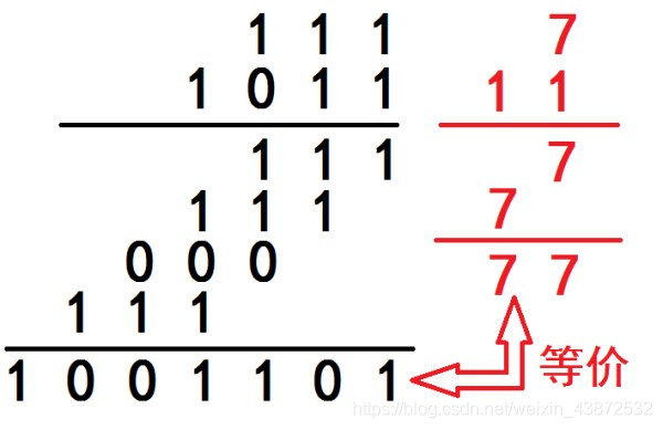 chart 4.4.1
( Two ) Split beat input principle
Two 8 The addition of binary numbers requires 16 Two input pins , But the space of the experimental board is limited , You have to enter only one at a time 8 Bit binary number , Two beats are input into the multiplier body mentioned above .
Complete the control of the beat through the design of the digital terminal , After the first number is input, set the number end to one , If the number is set successfully , Then the first light comes on . After the second number is set , Then set the number end to one . If the number is set successfully , Then the second light comes on . At this time, the input module outputs two multipliers at the same time .
5、 ... and 、 System design and simulation
( One ) Multiplier main module (mulity_8bit)

chart (5.1.1)
This module has 4 Inputs , One output , among clk by 1kHz Clock signal ,x and y For two 8 Bit binary multiplier .Start intention 1 Start counting at ,8 After a clock cycle result The end outputs the result .Start intention 0 The output is zero .
The module uses a module 10 Counter implementation , It can also be considered as a three state finite state machine .
S0: In the count for 0 It is the first state , Initialize multiplier , All variables are given initial values .
S1: In the count for 1~8 when , Complete the following three steps for each count
(1) Move the multiplier one bit to the right .
(2) According to whether the last digit of the multiplier is 1 Judge whether to add after shift .
(3) The product moves to the left 1 position
S2: In the count for 9 when , Output results .
See Appendix for the specific implementation code
The simulation waveform is shown in the figure (5.1.2), The simulation realizes
00100101×0010101 and 00000110×00000011

chart (5.1.2)
( Two ) Split input module (inp)
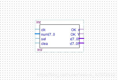
chart (5.2.1)
This module has 4 Inputs ,4 Outputs , among clk by 1kHz Clock signal ,num intention 8 Bit binary input ,set Set the number end ,clear It is the zeroing end .x,y by 8 Bit binary output .ok_x,ok_y Display the terminal for setting the number successfully .
Split beat input is realized by register , By testing set The number of times to X,Y assignment . The procedure is as follows :
- num The pin of is set to high and low level
- set Set up 1,Led_x Light up ,set Set up 0.
- num The pin of is set to the second number
- set Set up 1,Led_y Light up ,set Set up 0. Number setting completed .
- clear Restore to initial state .
- repeat 1~5 Step for the second set of inputs .
The above steps are realized by simulation , Pictured (5.2.2):

Pictured (5.2.2)
6、 ... and 、 The top design :

chart (6.1.1)
7、 ... and 、 Results simulation :
Software emulation :
chart (7.1.1)
Hardware testing :
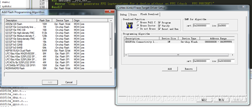
【1】 Select the corresponding chip :

chart (7.2.1)
【2】 Select three states for useless pins :

chart (7.2.2)
【3】 Assign pins :

chart (7.2.3)
【4】 Download tests
appendix :
(1)Inp.vhd:
LIBRARY IEEE;
USE IEEE.STD_LOGIC_1164.ALL;
USE IEEE.STD_LOGIC_ARITH.ALL;
USE IEEE.STD_LOGIC_UNSIGNED.ALL;
------------------------------------------------------
------------ Entity inp Realize split beat input data ---------------------
------------------------------------------------------
ENTITY inp IS
	PORT(
		clk    : IN STD_LOGIC;									-- The system clock
		num	 : IN STD_LOGIC_VECTOR(7 downto 0);			-- Type twice 8 Bit operands
		set	 : IN STD_LOGIC;									-- Set the number end , High active . num After the signal assignment of , Generate a high pulse and input a number
		clear  : IN STD_LOGIC;									-- Clear the zero end , High active .  Restore to initial state . set by 1 When not available
		OK_x	 : OUT STD_LOGIC;									-- The first number is successfully displayed on the display end
		OK_Y	 : OUT STD_LOGIC;									-- The second number is successfully displayed on the display end
		x	    : OUT STD_LOGIC_VECTOR(7 downto 0);		-- Output 8 Bit multiplier x
		y      : OUT STD_LOGIC_VECTOR(7 downto 0)			-- Output 8 Bit multiplier y
	);
END ENTITY inp;
------------------------------------------------------
---------------- Use process of split shot input ------------------------
------------------------------------------------------
----1. num The pin of is set to high and low level ------------------------------
----2. set Set up 1,Led_x Light up ,set Set up 0.---------------------
----3. num The pin of is set to the second number -----------------------------
----4. set Set up 1,Led_y Light up ,set Set up 0.---------------------
------------------------------------------------------
ARCHITECTURE BEHAVIOR OF inp IS
SIGNAL tem_x   : STD_LOGIC_VECTOR(7 downto 0);			--result The middle result of
SIGNAL tem_y   : STD_LOGIC_VECTOR(7 downto 0);			--result The middle result of
BEGIN
process(clk)
VARIABLE count : INTEGER:=0;
VARIABLE Flag  : INTEGER:=0;									--Flag by set Signal flag bit , Placed when the second clock signal arrives (count Already equal to 1) Get into y The assignment phase of .
begin
IF(clk'EVENT AND clk = '1')THEN
	IF(set = '1')THEN
		IF(count=0)THEN
			tem_x<=num;												-- if count by 0, Then assign the operand to x.
			OK_x<='1';												-- The first one. led The light is on .
			count := count + 1;
			Flag := 0;
		ELSIF(count=1 and Flag = 1)THEN
			tem_y<=num;												-- if count by 1, Then assign the operand to y.
			OK_y<='1';												-- Put the second led The light is on .
			count:= count+1;
			Flag := 0;
		END IF;
	ELSE
		Flag := 1;													--set Is zero ,Flag Record as 1.
		IF(clear = '1')THEN										--clear by 1 when , Clear status information .
			tem_x<="00000000";
			tem_y<="00000000";
			OK_x<='0';
			OK_Y<='0';
			count := 0;
			Flag := 0;
		END IF;
	END IF;
	x<=tem_x;
	y<=tem_y;
END IF;
end process;
END BEHAVIOR;
(2) mulity_8bit.vhd:
LIBRARY IEEE;
USE IEEE.STD_LOGIC_1164.ALL;
USE IEEE.STD_LOGIC_ARITH.ALL;
USE IEEE.STD_LOGIC_UNSIGNED.ALL;
------------------------------------------------------
---- Entity mulity_8bit Through serial multiplication 8 Bit binary multiplication ---------
------------------------------------------------------
ENTITY mulity_8bit IS
	PORT(
		clk    : IN STD_LOGIC;									-- The system clock
		x	    : IN STD_LOGIC_VECTOR(7 downto 0);			--8 Bit multiplier x
		y      : IN STD_LOGIC_VECTOR(7 downto 0);			--8 Bit multiplier y
		start	 : IN STD_LOGIC;									--START by 1 Time set number , by 0 When not working
		result : OUT STD_LOGIC_VECTOR(15 downto 0)		--16 A result
	);
END ENTITY mulity_8bit;
------------------------------------------------------
-------------------- Serial multiplication ---------------------------
------------------------------------------------------
ARCHITECTURE BEHAVIOR OF mulity_8bit IS
SIGNAL p     : STD_LOGIC_VECTOR(15 downto 0);			--p,t Is an intermediate variable , Record the result of multiplying one bit at a time
SIGNAL t     : STD_LOGIC_VECTOR(15 downto 0);
SIGNAL tem   : STD_LOGIC_VECTOR(15 downto 0);			--result The middle result of
SIGNAL y_reg : STD_LOGIC_VECTOR(7 downto 0);				--y Variable registers
BEGIN
PROCESS(clk,start)
VARIABLE count : INTEGER:=0;
VARIABLE Flag : INTEGER:=0;									-- Calculation completion flag , be equal to 1 When the calculation is completed , Terminate the calculation process , Output the result continuously
BEGIN
IF(clk'EVENT and clk = '1')THEN
	IF(start = '1')THEN
		IF(Flag = 0)THEN
			IF(count = 9) THEN 								   --count= 9 when , complete 8 After accumulating for several times, deposit the results in tem,ok Set up 1
				count := 0;
				tem <= p;
				Flag := 1;
			ELSIF(count = 0) THEN								--count = 0 when , Assign initial value to
				p(15 downto 0) <= "0000000000000000";
				y_reg <= y;
				t(7 downto 0)<= x(7 downto 0);
				t(15 downto 8)<="00000000";
				count := 1;
			ELSE														--count stay 1~8 when , Shift accumulation
				IF (y_reg(0) = '1') THEN
					p <= p + t;
				ELSE p <= p;
				END IF;
			y_reg(6 downto 0)<=y_reg(7 downto 1);			 --y_reg Moves to the right one
			y_reg(7) <= '0';
			t(15 downto 1) <= t(14 downto 0);				 --t The left one
			t(0) <= '0';
			count := count + 1;
			END IF;
		ELSIF (Flag = 1) THEN
			result <= tem;
		END IF;
	ELSIF(start = '0')THEN
		result <= "0000000000000000";
		Flag:= 0;
	END IF;
END IF;
END  PROCESS;
END BEHAVIOR;
版权声明
本文为[Why is it so difficult to name?]所创,转载请带上原文链接,感谢
https://yzsam.com/2022/04/202204210609243421.html
边栏推荐
- In shell programming, the shell file with relative path is referenced
- About the operation of unit file reading (I)
- Use bitnami / PostgreSQL repmgr image to quickly set up PostgreSQL ha
- Query the logistics update quantity according to the express order number
- Esp32 drive encoder -- siq-02fvs3 (vscade + IDF)
- 特征选择feature_selection--SelectKBest
- Hard core parsing promise object (do you know these seven common APIs and seven key questions?)
- Daily CISSP certification common mistakes (April 12, 2022)
- ctfshow-web361(SSTI)
- Introduction to QT programming
猜你喜欢
Resolution: cnpm: unable to load file \cnpm. PS1, because running scripts is prohibited on this system

ESP32 LVGL8. 1 - textarea text area (textarea 26)
Setting up keil environment of GD single chip microcomputer
7、 DOM (Part 2) - chapter after class exercises and answers
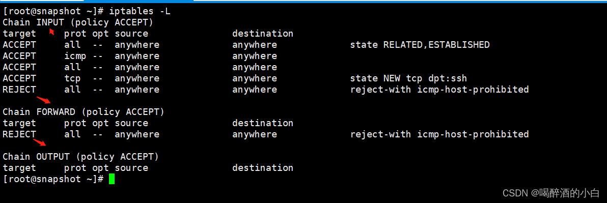
iptables初探

ESP32 LVGL8. 1 - bar progress bar (bar 21)

Multifunctional toolbox wechat applet source code

昇腾 AI 开发者创享日全国巡回首站在西安成功举行

Introduction to quantexa CDI syneo platform

教你用简单几个步骤快速重命名文件夹名
随机推荐
Notepad + + replaces tabs with spaces
机器学习实战 -朴素贝叶斯
Multifunctional toolbox wechat applet source code
MVVM model
Keil RVMDK compiled data type
Mysql database backup command -- mysqldump
CISSP certified daily knowledge points (April 12, 2022)
Nacos集群搭建和mysql持久化配置
教你用简单几个步骤快速重命名文件夹名
昇腾 AI 开发者创享日全国巡回首站在西安成功举行
CISSP certified daily knowledge points (April 13, 2022)
About the operation of unit file reading (I)
Loop path
Daily network security certification test questions (April 13, 2022)
Practice of Druid SQL and security in meituan review
解决:cnpm : 無法加載文件 ...\cnpm.ps1,因為在此系統上禁止運行脚本
Database computer experiment 4 (data integrity and stored procedure)
CANopen STM32 transplantation
Configure iptables
Use of regular expressions in QT